Gree GMV6 DC Inverter VRF Units Service Manual
328
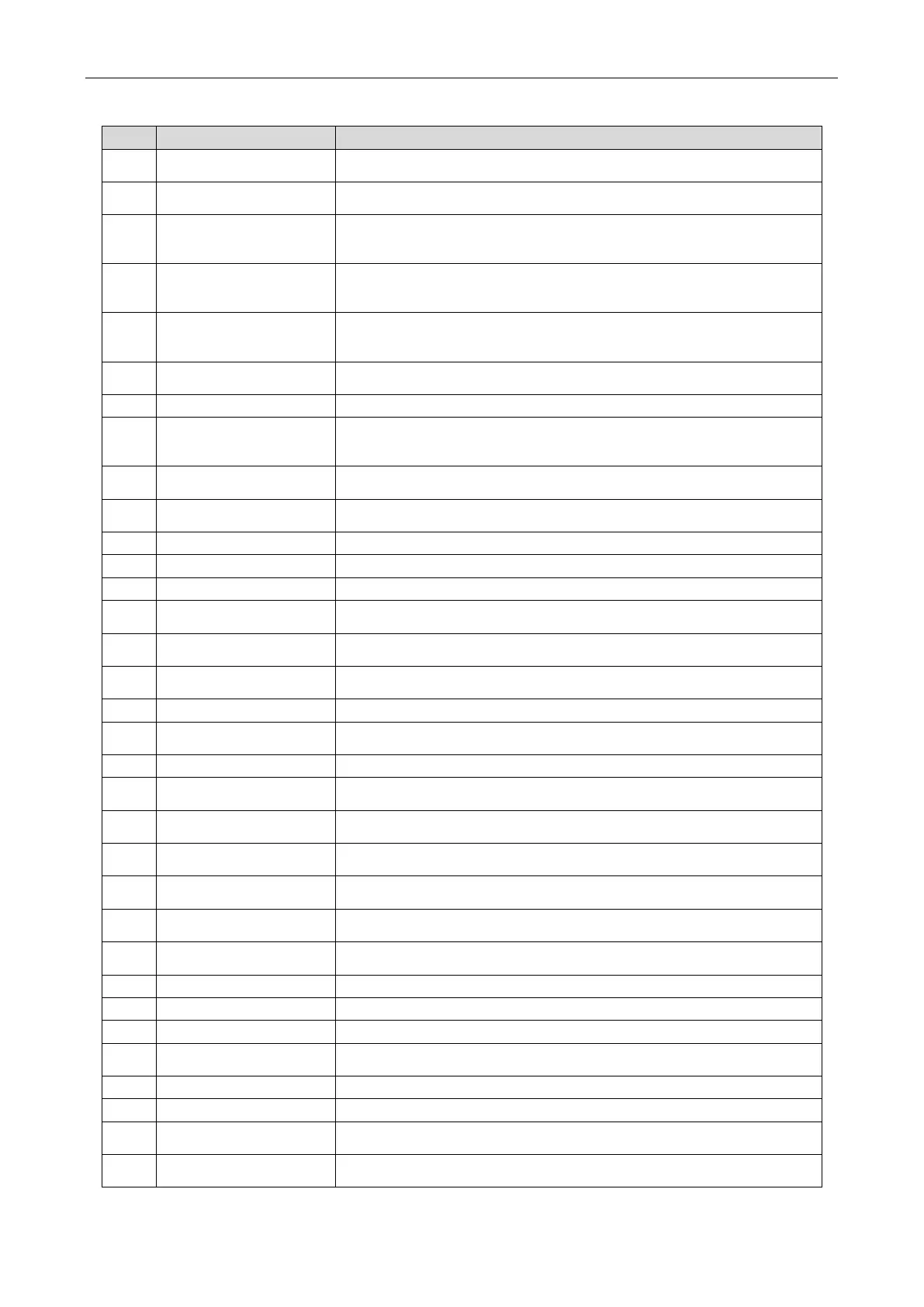
Appendix 7 Names and Functions of Components
No. Name Main Functions
1 Compressor
The compressor changes its speed according to the actual system need for
capacity adjustment.
2
Electrical heating belt of
the compressor
In the standby state, the oil temperature of the compressor is guaranteed to
prevent backflow.
3
sensor of the inverter
The
exhaust temperature of the compressor is detected to achieve the
purpose of controlling and protecting the compressor.
4
sensor of the inverter
The exhaust temperature of the compressor is detected to achieve the
purpose of controlling and protecting the compressor.
5 High pressure switch
When the exhaust pressure of the compressor exceeds the action value of the
high-pressure switch, the feedback signal immediately stops the operation of the
whole unit to achieve the purpose of protecting the compressor.
6 Oil separator
It separates the system's gas and oil to ensure the reliability of the
compressor.
7 Oil return solenoid valve It is used to control the connection of the compressor return oil pipeline.
8
electronic expansion
It is used to control the EVI capacity of the compressor.
9 One-way valve
It prevents high pressure gas from entering the compressor and quickly
balances the pressure on the compressor.
10 High pressure sensor
It detects real-time high voltage values of the system, protects the
compressor and realizes other control purposes.
11 4-way valve It is used for cooling and heating switching of the IDU.
It is used for outdoor heat exchange.
13 Fan It improves the heat exchange efficiency.
14
Defrosting temperature
sensor
It is used to detect defrosting.
15
Heating electronic
expansion valve
It adjusts the refrigerant in heating mode
16
Air by-pass valve/Gas
bypass solenoid valve
It is used to defrost the heat gas bypass and bottom of the outdoor heat
exchanger.
17 One-way valve It is used to control the flow direction of refrigerant.
18
Electronic expansion
valve of the sub-cooler
It is used to control the liquid pipe refrigerant subcooling degree during the
cooling operation of the system and reduce the loss of the pipeline capacity.
19 Sub-cooler It is used to control the liquid pipe subcooling degree.
20
Liquid outlet temperature
sensor of the sub-cooler
It is used to detect the liquid pipe temperature.
21
Inlet temperature sensor
of the gas-liquid separator
It is used to check the inlet temperature of the gas-liquid separator to prevent
liquid refrigerant from entering the system.
22
Gas inlet temperature
sensor of the sub-cooler
It is used to detect the gas pipe temperature.
23 Low pressure sensor
It is used to detect the low pressure of the system and prevent the operation
pressure from being too low.
24 Gas-liquid separator
It separates the gas and liquid and prevents liquid refrigerant from entering
the compressor.
25
Outlet temperature sensor
of the gas-liquid separator
It is used to detect the internal state of the gas-liquid separator and further
control the suction state of the compressor.
26 Capillary It throttles flows and reduces pressure.
27 Liquid valve It is closed after the unit is delivered from the factory.
28 Gas valve It is closed after the unit is delivered from the factory.
29
Low pressure measuring
valve
It is used to detect the system's operation low pressure value and refrigerant
charging.
30 Unloading valve It prevents a dead zone in the pipeline, which may cause over high pressure.
31 Gas bypass valve It is used to prevent the operation pressure from being too high or too low.
32
Solenoid valve of the sub-
cooler
It is used to control the flow direction of refrigerant for the enthalpy injection
of the sub-cooler.
33
Low-temperature oil-
return solenoid valve
It is used to control the connection of the compressor return oil pipeline.
 Loading...