1.1.
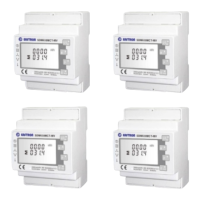
SDM630-Modbus V3 is a multi-function rail meter, it can accurately measure and display various power parameters in 1P2W/3P3W/3P4W:
voltage, current, power, frequency, active power, reactive power, forward power, reverse power, total harmonics, etc. The meter is suitable
for real-time power monitoring system, with multi-function, multi-purpose, high stability and long life characteristics. The meter is connected
with an external current transformer and is suitable for various high and low voltage power grids. The meter has RS485 communication
interface, supports the highest communication rate of 38400bps, can realize remote communication.
Overview
2.
3.
Unpacking
TPM-E(SDM630-Modbus V3) Three-phase
Smart Meter Quick Guide(MOD 3-10KTL3-XH)
Auxiliary power voltage range
85 ~ 275Vac or 120 ~ 380Vdc
Relative humidity(average annual)
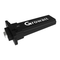
RS485 output for Modbus RTU
RS485 cable (standard length 15m)
Overview
Technical Parameters
A B C
4.
Dimension(Unit:mm)
5.
Installation
a.The network cable is described as follows:
b.Cut the crystal head, find out PIN1 and PIN5, and connect the
communication terminals according to the picture.
c.Connect the communication terminals as shown.
d.Connect the communication terminals to the 30-pin
communication terminals of the inverter.
e.The standard RS485 cable length is 15m.If need longer RS485
cable,please use an ethernet coupler to extend and make sure
RS485 cable less than 100m(the recommended length is less than
25m).
f.MOD XH system application block diagram wiring is as follows.
6.
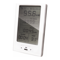
Button Definition And Display
There are four touch buttons on the panel, from top to bottom are “ESC(←)V/A”, “↑(Alt)MD/PH/HZ”, “↓(Shift)P”, “ENTER(→)E”. There are
two types of key operation: long press(Press for more than two seconds) and short press(Pressing time is less than one second).
Viewable content(short press)
Short press:
display voltage and current, ←
Long press: ESC
Phase voltage, Line voltage, Phase current, Neutral
current, Voltage harmonics, Current harmonics
Short press: display power factor and
frequency, ↑
Long press: Alt
Phase(Total) frequency, Total power factor, Phase(Total)
maximum current demand
Short press: display power, ↓
Long press: Shift
Phase(Total) active power, Phase(Total) reactive power,
Phase(Total) apparent power
Short press:
display electric energy, →
Long press: Enter
Total active electric energy, Total reactive electric energy,
Forward active electric energy, Reverse active electric
energy, Forward reactive electric energy, Reverse
reactive electric energy
ESC
Cut off
PIN 6
PIN 5
RS485B-
PIN 1 White Orange
RS485A+
PIN 5 White Blue
Meter Pin NO.
Description
Meter Connection
1/2/3/4
5/6/7/8
A
B
L1/L2/L3/N-in
L1/L2/L3/
N-out
RS485A
RS485B
Grid L1/L2/L3/N
AC connector & Load L1/L2/L3/N
COM Port Pin 5 RS485A3
COM Port Pin 6 RS485B3
Breaker Meter
Note:Please connect according to the above diagram, the meter power line and communication line need to be in one-to-one
correspondence.