English (GB)
11
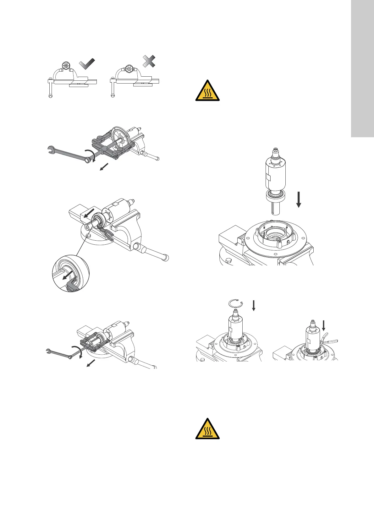
10. Wrap the rotor in a protective material, such as cardboard, to
protect it from scratches.
11. Place the rotor on the vice. Do not tighten the vice on the
rotor!
Fig. 15 Correct position of the rotor on the vice
12. Pull the flange from the rotor with a puller.
Fig. 16 Pulling the flange from the rotor
13. Remove the locking ring (188) from the shaft.
Fig. 17 Removing the locking ring
14. Remove the bearing (153) with a puller.
Fig. 18 Removing the bearing with a puller
Assembly
1. Place the rotor on a vice. Do not tighten the vice on the rotor!
2. Clean the bearing journal in the drive end with a clean cloth.
3. Heat the new bearing (153) to a temperature between 90 and
110 °C. Follow the instructions for the bearing and bearing
heater.
4. Fit the heated bearing on the drive end of the shaft.
5. Fit the locking ring (188) on the shaft.
6. Place the flange in the vice.
7. Clean the bearing seat with a clean cloth and lubricate the
bearing seat with anti-fretting paste.
8. Fit the rotor in the flange.
Fig. 19 Fitting the rotor in the flange
9. Fit the locking ring (187) so that the bearing is held by the
flange.
Fig. 20 Fitting the locking ring for the bearing
10. Clean the bearing journal in the non-drive end with a clean
cloth.
11. Heat the bearing (154) to a temperature between 90 and 110
°C.
12. Fit the heated bearing (154) on the shaft (172).
13. Remove the cardboard from the rotor when the bearings have
cooled down.
14. Check that the corrugated spring (158) is correctly fitted in the
stator housing.
15. Apply Loctite 5512 on the flange surface which seals against
the stator.
16. Gently insert the stator onto the rotor.
TM06 9031 1617TM06 9031 1617TM06 9033 1617TM06 9035 1617
CAUTION
Hot surface
Minor or moderate personal injury
- Use heat-resistant gloves.
TM06 9040 2016TM06 9042 1617 - TM06 9043 1617
CAUTION
Hot surface
Minor or moderate personal injury
- Use heat-resistant gloves.
 Loading...