3
sc1000 Panel Mount Bracket
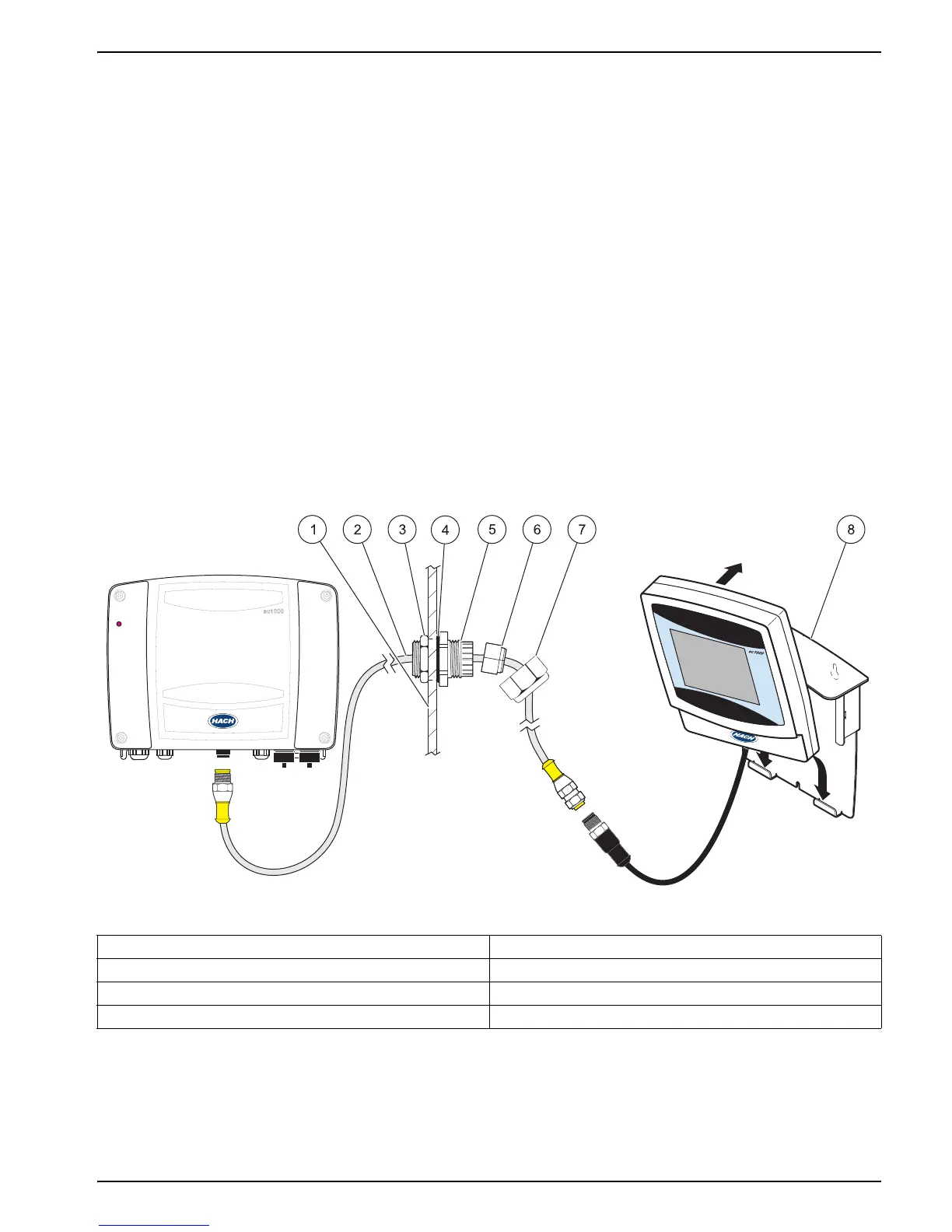
Modified strain relief installation
1. Thread the O-ring (Figure 2, item 4) onto the strain relief body.
2. Install the strain relief fitting into the panel pass-through hole. On the probe module
side of the panel, thread the lock nut (Figure 2, item 3) onto the strain relief and
hand-tighten.
3. Thread the extension cable through the strain relief (Figure 2, item 2).
4. Install the bushing (Figure 2, item 6) onto the extension cable. Note the orientation
in Figure 2.
5. At the clamping fingers (Figure 2, item 5), rotate the bushing counter-clockwise and
push the bushing into place in the strain relief.
6. Thread the nut (Figure 2, item 7) onto the extension cable and hand-tighten onto the
strain relief.
7. Connect the extension cable to the display module cable and the probe module.
Figure 2 Instrument components
1 Mounting panel 5 Clamping fingers
2 Extension cable (maximum 15 feet) 6 Bushing (split)
3 Lock nut (probe module side) 7 Lock nut (display module side)
4 O-ring (Cat. No. 5H1017) 8 Panel mount bracket

 Loading...