Do you have a question about the Haier 1U50S2SJ2FA and is the answer not in the manual?
| Brand | Haier |
|---|---|
| Model | 1U50S2SJ2FA |
| Category | Air Conditioner |
| Language | English |
Explains the components of the model name designation.
Provides important safety warnings and cautions for repair.
Details specific cautions to be followed during repair work.
Lists precautions to be taken after the repair is completed.
Outlines checks to perform after repair work is done.
Explains the purpose and meaning of icons used in the manual.
Details the voltage, phase, and frequency ratings.
Lists cooling and heating capacities and power input.
Provides dimensions, weight, and sound level specifications.
Lists electrical parameters like running and starting current.
Details specifications for major components like compressor and fan.
Covers refrigerant type, charge, piping, and protection ratings.
Illustrates the refrigerant piping for cooling operation.
Illustrates the refrigerant piping for heating operation.
Lists connectors for Control PCB (1) and Module PCB (2).
Provides additional notes on fuses, LEDs, and varistors.
Details main control specifications and operating parameters.
Explains compressor frequency control and operating scope.
Describes compressor startup, frequency rates, and calculation methods.
Describes how the outdoor fan speed is controlled.
Details EEV opening steps for cooling and heating modes.
Describes the operation of the four-way valve.
Outlines various protection mechanisms for the unit.
Provides warnings and procedures for diagnosing issues.
Lists electrical parameters for key components like compressor and reactor.
Lists common symptoms and their corresponding checks and measures.
Lists error codes, their indications, and reference pages.
Details how to diagnose thermistor failures and related issues.
Describes how to diagnose EEPROM errors.
Provides a flowchart for diagnosing indoor fan motor issues.
Explains how to diagnose outdoor DC fan motor faults.
Details diagnosis and troubleshooting for IPM protection.
Describes how to diagnose and resolve compressor over-current issues.
Details troubleshooting for communication faults between IPM and PCB.
Explains how to diagnose power supply voltage faults.
Details diagnosis for overheat protection due to discharge temperature.
Provides troubleshooting steps for indoor/outdoor communication faults.
Describes how to diagnose loss of synchronism issues.
Details troubleshooting for high work-intense protection.
Presents cooling capacity data across various temperature conditions.
Shows cooling power consumption data vs. temperature.
Displays cooling discharge pressure based on temperature.
Presents cooling suction pressure data vs. temperature.
Shows heating capacity data across various temperature conditions.
Presents heating power consumption data vs. temperature.
Displays heating discharge pressure based on temperature.
Shows heating suction pressure data vs. temperature.
Provides the circuit diagram for the outdoor unit control board.
Provides the circuit diagram for the module board.
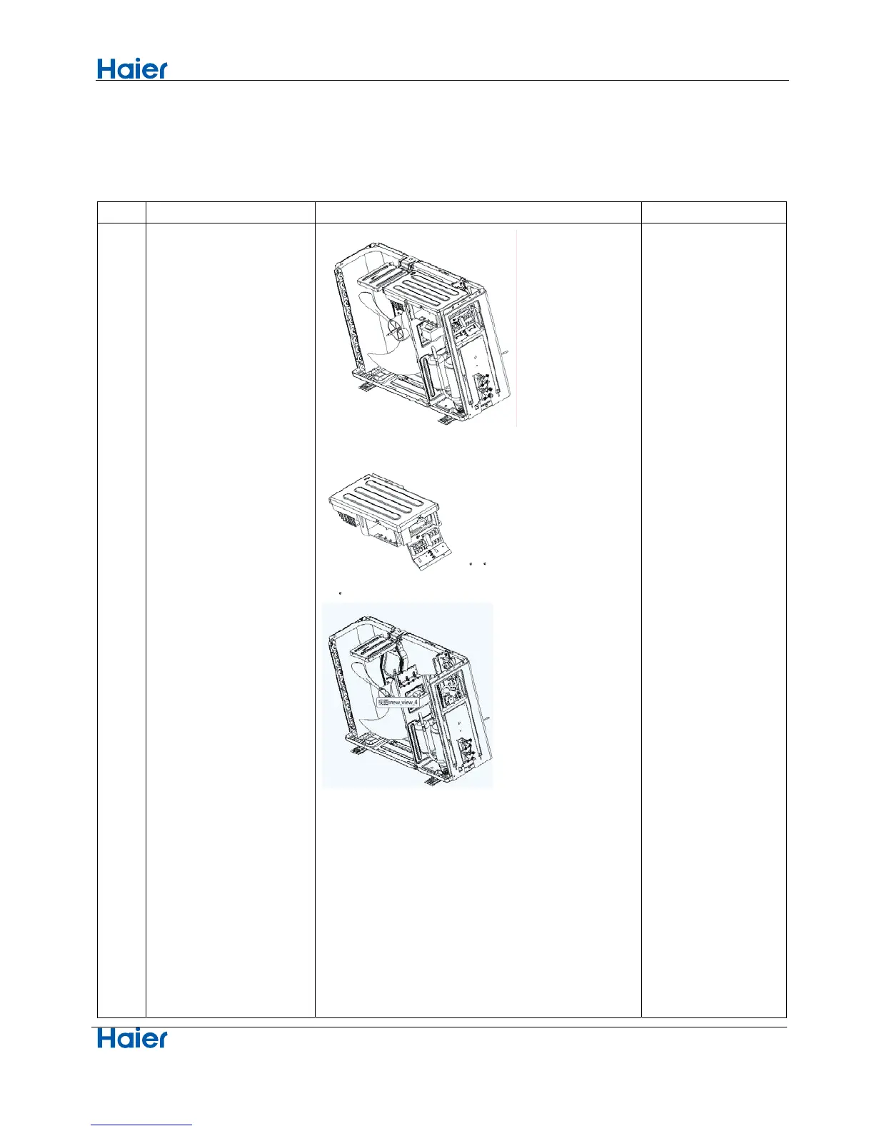
Details the procedure for removing the front panel of the outdoor unit.
Explains how to remove the top, side panels, and electrical box.
Describes how to remove air filters and the back protect net.
Details removing the side panel and cross beam.
Details removing fan motor bracket and compressor.
Describes loosening screws and removing the heat exchanger, pipes, and valves.