Precautions:
IMPORTANT: Disconnect
the
vehicle's
negative(-)
battery terminal
before beginning
the
installation.
•
/>Jways
wear protective eyewear
when
using tools.
• Choose a
safe
mounting location, away
from
moisture. Check
clearances on both sides of a planned mounting surface. Be sure that
screws
or
wires
will
not puncture brake
lines,
fuel
lines,
or wiring
harnesses
and that wire routing will not interfere with the
safe
vehicle
operation.
Use
caution when drilling or cutting
in
the mounting
area.
•
When
making electrical connections, make sure they are secure
and
properly insulated.
• If
you
must
replace
any
of the amplifier's
fuses,
use
the same type of
fuse
and
current rating
as
the original.
• To keep
the
amplifier cool, choose a location that provides
enough
a1r
circulation. such
as
under a seat or
in
the trunk.
• Do not mount the amplifier with the
heat
sink
facing
downward,
as
th1s
interferes with cooling.
• Mount the amplifier so that it
will
not be damaged by the
feet
of
backseat passengers or shifting cargo
in
the
trunk,
and
so that it
remains
dry.
•
Using
the amplifier
as
a template, mark the locations of
the
holes on
the mounting surface.
•
Drill
p1lot
holes
1n
the mounting surface.
• Attach the amplifier to the mounting surface with four appropriate
mounting screws
(not
included). Recommended:
#8
Phillips-head
sheet
metal screws.
~TAC.E
NOTE:
You
may find it more convenient to
make
all
of the
connections to the amplifier before
you
permanently mount it.
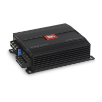
• Power/protect indicator:
The light
will
illuminate in blue when the amp is
receiving
power and
playing.
The
indicator will illuminate
in
red
if the amp enters Protect
mode
in
the event of conditions such
as
over/under voltage. short
circuit,
amplifier output circuit
failure,
or excessive heat.
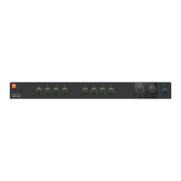
•
Power
Input Connectors:
• Power:
Run
power wire from the
+12V input
to
the
posrtive
terminal
of
the
vehicle's battery. Insert bare wire
into the
terminal
on the amplifier,
then
tighten
the
setscrew with a
Phillips
screwdriver.
•
Install
an
appropriate
fuse
holder
and
fuse
(20A
minimum
for
Stage
A6002
and
30A
minimum
for
Stage
A6004
and
A3001,
and
40A
minimum
for
A9004)
within
18"
(457mm)
of
the
battery.
Make
sure
the
wire
is
not
damaged
or pinched
during
installation.
Install
protective
grommets
when
routing
wires
through
the
bulkhead
or
other
sheet
metal.
Use
larger-gauge
wiring
for
longer
runs.
o Stage A6002 minimum wire
size:
;, 1 0 gauge
o
Stage A6004, A9004,
A3001
minimum
wire
size:
;,8
gauge
+
12
volt
Remote
Groond
t t t
To
in-dash
rece
iver
0 0
ggg g (===:Jgg
~•o
c
cccccc
c o
---
o T
Fuse
0
18" (46cm)
Power
wire
r
r'?----';:>-.,_1_
Vehicle
battery
Vehicle
chassis
Ground
wire
• Ground:
Run
a
wire
(the
same gauge as the power
wire)
from the
GND
input to a factory bolt
in
the
vehicle's chassis
(see
illustration
below).
NOTE:
Remove
any
paint from the chassis for best contact.
Use
a star
washer below
the
ring
connector for a secure connection.
Factory
Bolt
Note:
Remove
any
pamt
below
ring
connector
Ring
Coo
n
ector
Star
Washer
Ground
Wire
\
• Remote: Connect a 20-gauge wire
from
the
"Remote
Out"
lead
of
the
source unit to the
REM
input.
This
lead
turns the
amplifier
on
when
using
low-level
input
s~gnals.
If
your
stereo
has
no
"Remote
Out"
lead,
connect the
amplifier's
REM
input to switched accessory power.
• Fuses:
• Replace only with
fuses
of the
same
amperage:
o Stage A6002: 20A
o Stage A6004
and
A3001 :
15A
x 2
o
Stage A9004: 20A x
2
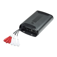
•
Speaker
Output Connectors:
Connect the speakers to these
terminals,
observ1ng
proper polarity (connect
each speaker's positive(+)
lead
to the appropriate positive(+)
terminal,
and
negative(-)
lead
to
the
appropriate negative(-)
terminal.
Stage
A6002
•
The
Stage A6002 features L+,
L-,
R+,
and
R-
terminals.
• 2-channel operation: Connect the left speaker to the
L+
and
L- terminals,
and the
right speaker
to
the
R+
and
R-
terminals.
Right
speaker
o Bridged operation: Connect the positive wire
from
the
single
speaker or subwoofer to
the
R+
terminal,
and
the negative wire
from
the speaker or subwoofer to the
L-
terminal.
 Loading...