Copyright © 2020 Haskris REV102920
9
www.haskris.com
776 North Oaklawn Avenue, Elmhurst, Illinois 60126 USA ph: +1-847-956-6420 | fx: +1-847-956-6595 | email: service@haskris.com
Operation and Maintenance
Haskris LX-Series, R-Series, WW-Series, OPC-Series
Section 8: Bypass Pressure Relief Valve
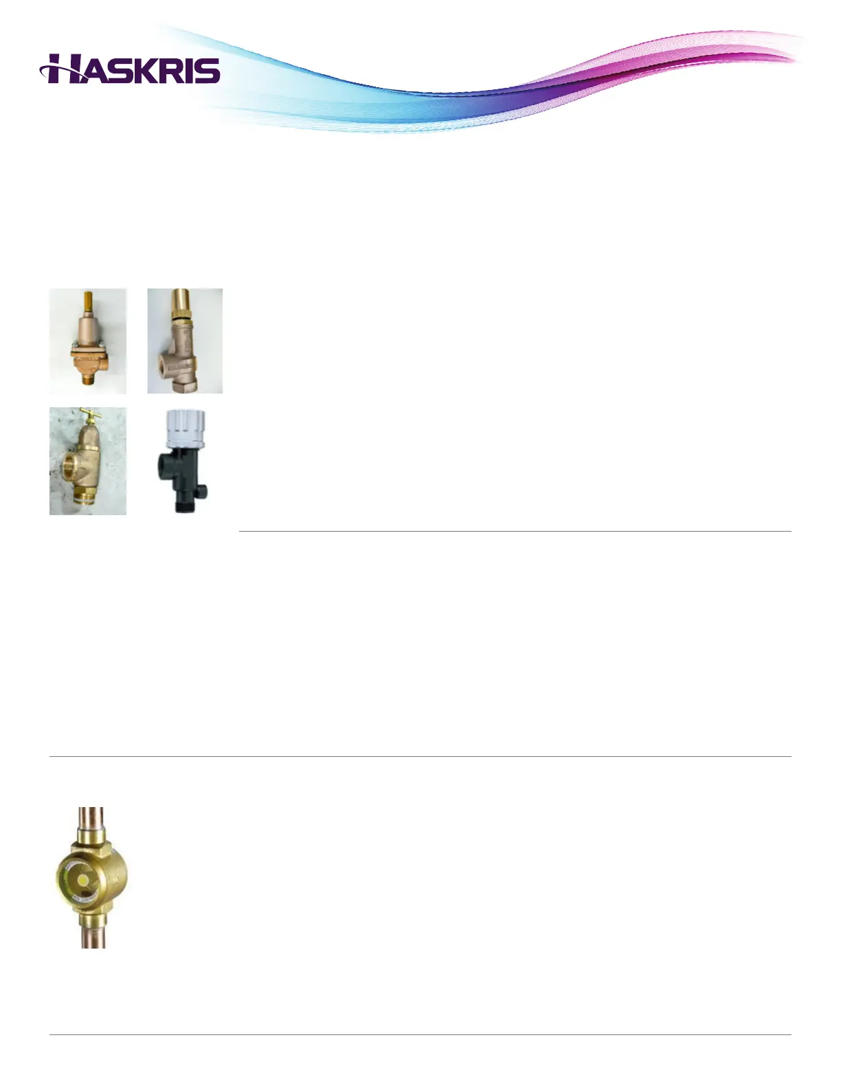
Section 8.1: Valve Setting Procedure
1. To nd the current pressure setting of the bypass valve, restrict the supply line by closing a hand
valve or kinking the hose. The pressure gauge indicates the current setting.
2. Remove the brass cap on the top of the adjustment screw, and loosen the locknut at the base.
3. Adjust the screw inward (clockwise) to increase the pressure setting. Adjust the screw outward
(counterclockwise) to decrease the pressure setting. Do not completely remove the screw. This
will cause a metal disc to fall off of the spring, requiring reassembling.
4. When the adjustment is complete, tighten the locknut and replace the cap.
Section 9: Refrigerant Sight Glass and Moisture Indicator
• Some refrigerated units include a liquid line sight glass and moisture indicator.
• This helps identify if the unit is low on refrigerant or if the refrigerant is contaminated.
• The sight glass should be clear and indicate “DRY” when the compressor is running.
• Constant bubbles owing indicate that the system is low on refrigerant.
• “WET” indicates that the refrigerant is contaminated.
• Turbulence and bubbles are normal immediately after the compressor turns ON, and immediately
after it turns OFF.
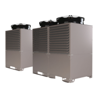
• Units with a positive displacement or turbine pump include one of the four types of modulating
bypass pressure relief valves shown at left.
• The valve has been preset from the factory for a maximum pressure in order to limit the supply
pressure to the application.
• The valve diverts ow whenever the running pressure of the system approaches the bypass
pressure setting.
• The bypass pressure setting must be above the pressure drop of the application and closed
loop piping.
• The running pressure of the system will increase if a restriction develops. This could occur due
to a closed valve or particle accumulation.
 Loading...