Gas line testing:
The appliance and its gas connection shall be leak test-
ed before placing in operation. The heater and its individual
shutoff valve must be disconnected from the gas supply
piping system during any pressure testing of that system
at test pressures in excess of 1⁄2 psig. The heater must be
isolated from the gas supply piping system by closing its
individual manual shutoff valve during any pressure testing
of the gas supply piping system at test pressure equal to or
less than 1⁄2 psig.
The gas supply line must be capped when not connect-
ed. After pressure testing, reconnect the gas piping to the
gas valve. Turn gas supply on and test all pipe and pilot tub-
ing joints for leaks. Use a soap and water solution. Bubbles
forming indicate a leak. Never use a open flame (match,
lighter, torch, etc.) as a leak could cause an explosion
or injury. Shut off gas and fix even the smallest leak imme-
diately. Be sure to leak test the main burner fittings using
the above procedure once the heater is in operation.
Gas pressure test procedure:
The following gas pressure adjustments are important to
proper operation of the heater. Incorrect settings can cause
improper operation.
1. Turn pump, main gas valve and heater power on. Start
heater following lighting instructions.
2. Using a manometer, determine the inlet gas pressure.
The inlet gas pressure must not exceed 10.5” W.C.
(water column pressure) for Natural gas or 13” W.C.
for Propane gas. Exposure to higher pressures can
damage the gas control valve, causing leaks or dia-
phragm rupture. This damage could result in fire, explo-
sion or burner overfiring leading to carbon monoxide
poisoning. The inlet gas pressure must not be below 3.0”
W.C. for Natural gas and for Propane. The heater may
fail to operate at low inlet gas pressures. If the inlet gas
pressure is too high or too low, the installer must contact
the gas supplier and request that the inlet pressure to
the heater be adjusted.
3. Using a manometer, determine the gas operating pres-
sure. Manifold pressure for both natural and propane gas
is 2.0” W.C. The gas valve is preset to operate at this
pressure, no adjustment is necessary.
Section II. Installer
4
1. Clean filter thoroughly.
2. Set heater thermostat to highest setting.
3. Start filter pump. Make sure all air is out of water
lines and complete system is full of water.
4. Place a 5/64” allen head wrench in the adjusting
socket on the front of the switch and turn it
clockwise to increase the pressure required to close
the switch (this may be required if the heater is
installed more than 4 feet below water level).
5. To check operation, turn the pump on and off several
times. The heater should shut off immediately when
the pump is shut off.
Distance from Tank Iron Tubing
(propane) Pipe
0 to 25 feet 3/8” 5/8”
25 to 100 feet 1/2” 3/4”
100 to 200 feet 3/4” 7/8”
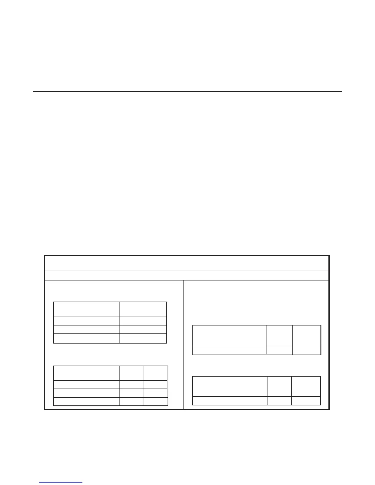
Follow local gas codes for proper gas line material selection (copper, iron or plastic etc.)
LOW PRESSURE PROPANE GAS PIPE SIZING “SECOND
STAGE” (Based upon gas pressure of 11 inches W.C. inlet
pressure at a pressure drop of 05 inch W.C.)
Gas pipe size:
Figure 4
LOW PRESSURE NATURAL GAS Pipe Sizing:
(Based upon gas pressure of 0.5 psig or less and a
pressure drop of 0.5” W.C.)
LOW PRESSURE PROPANE GAS PIPE SIZING
“SINGLE STAGE”: (Based upon gas pressure of
11” W.C. inlet pressure and a 0.5” W.C. pressure drop)
Distance from Meter Iron
(Natural Gas) Pipe
0 to 25 feet 1/2”
25 to 100 feet 3/4”
100 to 200 feet 1”
It is VERY IMPORTANT when installing a propane heater on a
two (2) stage regulation system, to follow the gas line sizing
chart below—without exception.
HIGH PRESSURE “TWO STAGE” SYSTEMS:
MGH PRESSURE PROPANE GAS PIPE SIZING
”FIRST STAGE”: (Based upon gas pressure of 10 psig inlet
pressure at a pressure drop of 1 psi.)
Distance from outlet of Iron
1st stage regulator to Pipe Tubing
inlet of 2nd stage regulator
0 to 200 feet 1/2” 1/2”
Distance from outlet of Iron
2nd stage regulator to Pipe Tubing
inlet of gas valve
0 to 10 feet 1/2” 1/2”
 Loading...