39 ONLYUSEGENUINEHAYWARDREPLACEMENTPARTS
51300803801REVB
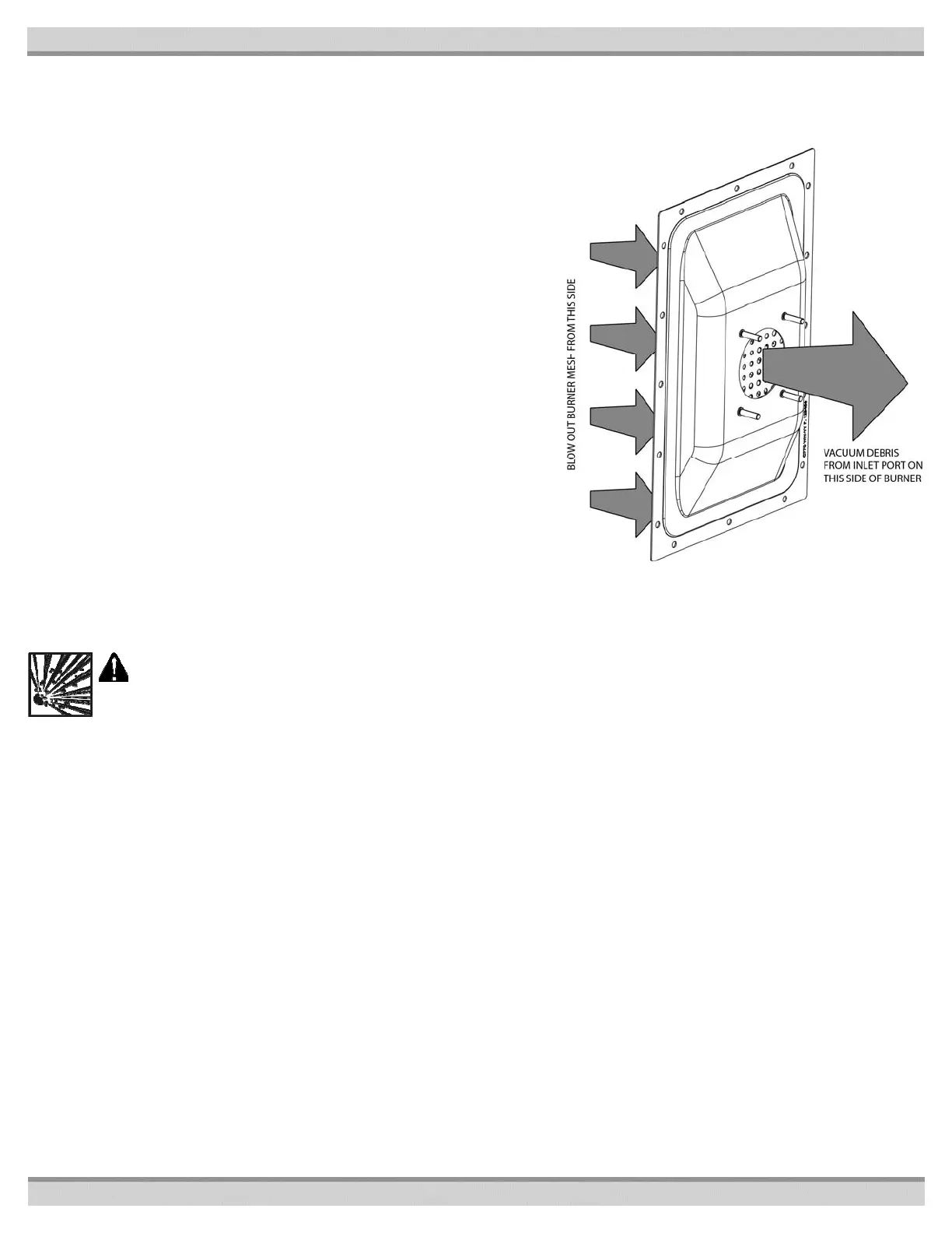
BURNER INSPECTION AND CLEANING:
Turn the heater “OFF” and allow enough time for the heater to cool down before performing the following process. Allowing the filter pump to
remain running will speed up the cooling process.
1. Turn pump, main gas valve, and heater power “OFF”.
2. Loosen the flare nut securing the gas manifold to the blower assembly (see Fig-
ure 19: Location of Components).
3. Remove the blower wiring harness from the control board.
4. Remove the screws securing the burner to the combustion chamber and remove
the blower and burner from the unit as a single sub-assembly.
5. Remove the four nylon lock nuts securing the blower and burner together.
6. Clean the burner by blowing shop air backwards through the burner (see Figure
28).
7. Dump any debris that becomes dislodged through the inlet opening of the burner
and use a shop vac to remove any dust or small particles remaining.
8. Be sure to inspect the fiberglass burner mounting gasket and the silicone gasket
between the burner and blower before re-assembling. If either gasket has any
damage. Replace it before putting the heater back into service.
NOTICE: It is highly recommended to replace the burner and blower mounting
gaskets each time the components are disassembled for cleaning, inspection, or
service.
9. Re-assemble the heater by reversing the above steps.
Tighten the four nuts securing the blower to a torque of 5 ft-lbs.
Tighten the flare nut securing the gas manifold to the blower to a torque of
50 ft-lbs.
10. Turn the gas supply “ON”. Use a soapy water solution to check for leaks. Bubbles
forming indicate a leak.
WARNING: EXPLOSION HAZARD The use of an open flame to check for gas leaks could cause an explosion resulting in
severe injury and/or death
11. Turn pump, gas valve, and heater power “ON”. Test fire the heater by following the GAS PRESSURE TEST PROCEDURE.
IGNITER AND/OR FLAME SENSOR REPLACEMENT: Refer to Figures 1, 19, 20, and 21 as needed.
1. Turn pump, gas supply, and heater power “OFF”.
2. Remove the molded Header Controls Cover by removing the four screws securing it to the water head side sheet metal.
3. Remove the Control Access Cover on top of the unit.
4. Disconnect the igniter and flame sensor wires from the ignition control board.
5. Remove the two screws securing the igniter to the front of the combustion chamber.
6. Remove the two screws securing the flame sensor to the front of the combustion chamber.
7. Pull the igniter straight back until it is free of the combustion chamber refractory and header.
8. Pull the flame sensor straight back until resistance is felt. Rotate the flame sensor 180° and lift up and out to remove it from the combus-
tion chamber.
9. Remove the old gasket from the front of the combustion chamber.
10. Replace the gasket, igniter, and flame sensor and reverse the above procedure to reassemble unit.
Figure 29: Burner Cleanout
 Loading...
