ELECTRICAL GUIDE – 60 CYCLE MOTORS – SINGLE PHASE
MOTOR
HP KW
VOLTS
Circuit Breaker
RATING - AMPS
RECOMMENDED
WIRE SIZE
0-50’, 0-15m
3/4
1
1 1/2
2
2 1/2
3
.55
.75
1.12
1.55
1.87
2.20
115
230
115
230
115
230
115
230
230
230
15
15
20
15
30
15
30
15
20
20
N°14
N°14
N°12
N°14
N°10
N°14
N°10
N°14
N°12
N° 12
www.haywardcanada.com
TROUBLE SHOOTING GUIDE
SERVICE AND REPAIRS
Consult your local authorized Hayward dealer or service center.
No pumps or motors may be returned directly to the factory without the
express written authorization of Hayward Pool Products Canada, Inc.
A. MOTOR WON'T START
B. MOTOR CUTS OUT – Check for:
C. MOTOR HUMS BUT DOES NOT START
D. PUMP WON'T PRIME
E. LOW FLOW – Generally, Check for:
F. NOISY PUMP – Check for:
Check for improper or loose connections, open
switches or relays, blown circuit breakers or fuses.
Manually check rotation of motor shaft for free
movement and lack of obstruction.
Wiring, loose connections, etc.
Low voltage at motor (frequently caused by
undersized wiring.
Binding and overload. (Amperage reading)
NOTE: Your Hayward pump motor is equipped
with Automatic Thermal Overload Protection.
The motor will automatically shut o, under
normal conditions, before heat damage build-up,
due to an improper operating condition, can
occur. The motor will auto-restart when safe heat
level is reached.
– Check for:
Centrifugal switch stuck in open position.
Binding of motor shaft.
Make sure pump/strainer housing is lled with
water, and that cover O-Ring is clean and
properly seated. Make sure strainer cover is
locked rmly in position.
Make sure all suction and discharge valves are
open and unobstructed, and that pool water
level is above all suction openings.
If pump develops a vacuum, check for blocked
suction line or strainer, or air leak in suction
piping.
If pump does not develop a vacuum and pump
has sucient "priming water":
Tighten all bolts and ttings.
Check voltage to make sure pump is up to speed.
Open pump and check for clogging and
obstruction.
Remove and replace shaft seal.
Clogged or restricted strainer or suction line;
undersized pool piping.
Plugged or restricted discharge line of lter (high
discharge gauge reading).
Air leak in suction (bubbles issuing from return
ttings).
Pump operating underspeed (low voltage).
Plugged or restricted impeller.
Air leak in suction causing rumbling in pump.
Cavitation due to restricted or undersized suction
line and unrestricted discharge lines. Correct
suction condition or throttle discharge lines, if
practical.
Vibration due to improper mounting, etc.
Foreign matter in pump housing.
Motor bearings made unserviceable by wear,
rust, or continual overheating.
1.
2.
1.
2.
3.
1.
2.
1.
2.
3.
4.
a.
b.
c.
d.
1.
2.
3.
4.
5.
1.
2.
3.
4.
5.
SEAL CHANGE INSTRUCTIONS
SP-3000 SERIES
GENERAL
Exercise extreme care in handling and installing the new seal and seat assembly.
The lapped and polished surfaces may easily be damaged by dirt or scratching.
For safety, all service must be performed with all power shut o.
REMOVING THE MOTOR ASSEMBLY
Remove the (6) 3/8" x 2" hex head bolts which hold the
motor assembly to the pump/strainer housing.
Slide the motor assembly out of the pump/strainer
housing, exposing the diuser. Pull the diuser o of the
seal plate, exposing the impeller. (The diuser may
remain in the pump/strainer housing. To remove, pull it
straight out of the strainer housing).
REMOVING THE IMPELLER
Remove the motor end cover by removing the (2) screws.*
To hold motor shaft from turning, carefully slide a 7/16"
wrench between the capacitor and the protector switch,
and rotate the impeller so the wrench ts over the (2) ats
on motor shaft.
Rotate the impeller counter-clockwise and remove. The
spring portion of the seal assembly is now exposed. Note
carefully the position of the spring seal, and remove it.
NOTE: Replace motor cover to protect delicate motor
parts.
REMOVING THE CERAMIC SEAT
Remove the seal plate. Note the notch on the top of the
plate and the mating lug on the top of the motor
mounting bracket.
Press the ceramic seat with o-ring out of the seal plate. If
tight, use a small screwdriver to tap seat out.
STOP — Clean all recesses and parts to be reassembled.
Inspect gaskets and replace if necessary.
1.
2.
3.
4.
5.
6.
7.
* For motors without removable end cover — pry o cap at rear center of motor. Place large screwdriver in slot
at end of shaft to keep shaft from turning.
NOTE: For models equipped with Part No. SP-3005-R or SP-3021-R Impeller Ring - remove impeller ring from
front hub of impeller. When reassembling, be sure to replace it on impeller hub, larger end facing diuser,
before placing diuser over the impeller.
www.haywardcanada.com
SEAL INSTALLATION
Clean and lightly lubricate the impeller hub and seal
recess in the seal plate with silicone or Jack’s N° 327 o-ring
lube.
Gently wipe the black, polished surface of the spring seal
assembly with a clean, soft cotton cloth. Press the spring
seal assembly onto the impeller hub — black polished
surface facing away from the impeller.
Gently wipe the polished face of the ceramic seat with a
soft, cotton cloth. Lubricate the o-ring on the ceramic seat
and press it rmly and evenIy into the recess in the seal
plate — polished side facing out.
Place the seal plate onto the motor mounting bracket
aligning the positioning lug and guide.
REPLACING THE IMPELLER AND DIFFUSER
Screw the impeller onto the motor shaft in a clockwise
direction. Tighten snugly by holding motor shaft with
wrench.
Place the diuser over the impeller onto the seal plate,
tting positioning lug between the two guides.
REPLACING THE MOTOR ASSEMBLY
Slide the motor assembly, with the diuser in place, into
pump/strainer housing, being careful not to dislodge the
diuser.
Fasten assembly to housing using the (6) 3/8" x 2" bolts.
(Be sure housing gasket is in place). Tighten alternately
and evenly.
8.
9.
10.
11.
12.
13.
14.
15.
IS-3005X7 HC-07
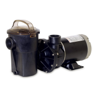
OWNER'S GUIDE
Your Hayward self-priming centrifugal pump has
been quality-built and engineered to give you many
years of ecient, dependable, corrosion-free
service. The advanced design reduces operation and
maintenance to simple, common-sense procedures.
GENERAL TIPS ON PUMP INSTALLATION
Locate the pump as close to the pool as practical and run
suction line as direct as possible. This cuts down on friction loss
through pipe and ttings.
Never overtighten pipe connections — use only pipe sealants
formulated specically for Plastics, i.e. Teon Tape, Permatex No.
2, etc.
Suction line should have continuous slope from lowest point in
line. Make sure suction joints are tight. Suction pipe should be
as large or larger than discharge pipe.
Damp, non-ventilated locations should be avoided. Motors
require free circulation of air to aid in cooling.
Insure electrical supply agrees with motor voltage, phase and
cycle, and that wire size is adequate for the HP/KW rating and
distance from power source. Motor must always be properly
grounded. Electrical circuits should be protected by proper size
ground fault circuit interrupter (GFCI). Electrical wiring should
be performed by qualied personnel, and must conform to local
codes and regulations.
STARTING AND PRIMING INSTRUCTIONS
Fill strainer/housing with water to suction pipe level. Never
operate the pump without water. Water acts as a coolant and
lubricant for the mechanical shaft seal.
Open all suction and discharge valves, as well as air bleed (if
available) on lter. (The air that is to be displaced from the
suction line must have someplace to go.)
Turn on power and allow a reasonable time for priming. Five
minutes is not unreasonable. (Priming time depends on suction
lift and horizontal length of suction piping). If pump will not
start, or will not prime, see TROUBLE SHOOTING GUIDE on back
page.
MAINTENANCE
Clean strainer basket regularly. Do not strike basket to clean.
Inspect strainer cover gasket regularly and replace as
necessary.
Hayward pumps have self-lubricating motor bearings and
shaft seals. No lubrication is necessary.
Keep motor housing clean. Insure air vents are free from
obstructions, debris, etc.
Occasionally, shaft seals must be replaced, due to wear or
damage. See instructions
WlNTERIZING/STORAGE
Drain pump by removing drain plug(s) and store in strainer
basket.
Disconnect electrical wires and pipe connections, and store
pump in a dry, well-ventilated room. Or:
Disconnect electrical wires. Remove six (6) bolts holding
bracket and motor assembly to Strainer/Housing and store
assembly in a dry, well ventilated room. Protect remaining
Strainer/Housing assembly from the elements by covering.
NOTE: Before Re-Activating pump, thoroughly clean and remove
scale, dirt, etc.
1.
2.
3.
4.
MANUFACTURED EXCLUSIVELY BY HAYWARD
2880 PLYMOUTH DRIVE, OAKVILLE, ONTARIO L6H 5R4 • 1-888-238-POOL
® Hayward Pool Products Canada, Inc. -- Licensee
www.haywardcanada.com
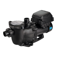
Super II Pump
™
1.
2.
8
17
7
15
18
9
3
10
11
22
19
4
16
13
5
12
20
2
21
1
6
14
1
2
3
4
5
6
7
8
9
10
11
12
13
14
15
16
17
18
19
20
21
22
1
1
1
1
1
6
1
2
2
2
2
1
1
1
1
1
1
1
1
4
1
1
SPX1607Z1M
SPX3000F
RSX750A2
SPX3000BN
SPX3000T
SPX1600Z4
SPX3000D
SPX1600P
SPX1600N2
SPX1700FG
SPX1600Z5
SPX3020E
SPX1600Z2
SPX3000Z26
SPX3000S
SPX3005C
SPX3005R
SPX3000M
SPX1600R
SPX0125Z4
SPX0125F
SPX3000GA
REF.
NO.
DESCRIPTION
QTY
MODEL
SP-3005X7
MODEL
SP-3007X10
MODEL
SP-3010X15
MODEL
SP-3015X20
MODEL
SP-3020X25
MODEL
SP3025X30
Motor
Motor Mounting Plate
RS Pump Housing
Diffuser
Housing Gasket
Housing Cap Screw
Strainer Cover
Hand Knob
Swivel Nut
Drain Plug & Gasket
Mounting Foot Cap Screw
Seal Plate
Seal Assembly
Flat Washer (set of 6)
Strainer Cover O-Ring
Impeller
Impeller Ring
Basket
Diffuser Gasket
Motor Cap Screw
Slinger
Mounting Bracket w/Adapter
PART NUMBER
SPX1610Z1M
SPX3000F
RSX750A2
SPX3000BN
SPX3000T
SPX1600Z4
SPX3000D
SPX1600P
SPX1600N2
SPX1700FG
SPX1600Z5
SPX3020E
SPX1600Z2
SPX3000Z26
SPX3000S
SPX3007C
SPX3005R
SPX3000M
SPX1600R
SPX0125Z4
SPX0125F
SPX3000GA
SPX1615Z1M
SPX3000F
RSX750A2
SPX3021BN
SPX3000T
SPX1600Z4
SPX3000D
SPX1600P
SPX1600N2
SPX1700FG
SPX1600Z5
SPX3020E
SPX1600Z2
SPX3000Z26
SPX3000S
SPX3010C
SPX3005R
SPX3000M
SPX1600R
SPX0125Z4
SPX0125F
SPX3000GA
SPX1620Z1M
SPX3000F
RSX750A2
SPX3021BN
SPX3000T
SPX1600Z4
SPX3000D
SPX1600P
SPX1600N2
SPX1700FG
SPX1600Z5
SPX3020E
SPX1600Z2
SPX3000Z26
SPX3000S
SPX3016C
SPX3021R
SPX3000M
SPX1600R
SPX0125Z4
SPX0125F
SPX3000GA
SPX1625Z1M
SPX3000F
RSX750A2
SPX3021BN
SPX3000T
SPX1600Z4
SPX3000D
SPX1600P
SPX1600N2
SPX1700FG
SPX1600Z5
SPX3020E
SPX1600Z2
SPX3000Z26
SPX3000S
SPX3021C
SPX3021R
SPX3000M
SPX1600R
SPX0125Z4
SPX0125F
SPX3000GA
SPX1630Z1M
SPX3000F
RSX750A2
SPX3021BN
SPX3000T
SPX1600Z4
SPX3000D
SPX1600P
SPX1600N2
SPX1700FG
SPX1600Z5
SPX3020E
SPX1600Z2
SPX3000Z26
SPX3000S
SPX3026C
SPX3021R
SPX3000M
SPX1600R
SPX0125Z4
SPX0125F
SPX3000GA
www.haywardcanada.com