ELECTRICAL GUIDE – 60 CYCLE MOTORS – SINGLE PHASE
MOTOR
VOLTS
Circuit Breaker
RATING - AMPS
RECOMMENDED
WIRE SIZE 0-50’, 0-15m
HP KW
1
1 1/2
.75
1.12
115
115
20
20
No. 12
No. 12
TROUBLE SHOOTING GUIDE
SERVICE AND REPAIRS
Consult your local authorized Hayward dealer or service center.
No pumps or motors may be returned directly to the factory without the
express written authorization of Hayward Pool Products Canada, Inc.
A. MOTOR WON'T START
B. MOTOR CUTS OUT – Check for:
C. MOTOR HUMS BUT DOES NOT START
D. PUMP WON'T PRIME
E. LOW FLOW – Generally, Check for:
F. NOISY PUMP – Check for:
Check for improper or loose connections, open
switches or relays, blown circuit breakers or fuses.
Manually check rotation of motor shaft for free
movement and lack of obstruction.
Wiring, loose connections, etc.
Low voltage at motor (frequently caused by
undersized wiring.
Binding and overload. (Amperage reading)
NOTE: Your Hayward pump motor is equipped
with Automatic Thermal Overload Protection.
The motor will automatically shut o, under
normal conditions, before heat damage build-up,
due to an improper operating condition, can
occur. The motor will auto-restart when safe heat
level is reached.
– Check for:
Centrifugal switch stuck in open position.
Binding of motor shaft.
Make sure pump/strainer housing is lled with
water, and that cover O-Ring is clean and prop-
erly seated. Make sure strainer cover is locked
rmly in position.
Make sure all suction and discharge valves are
open and unobstructed, and that pool water
level is above all suction openings.
If pump develops a vacuum, check for blocked
suction line or strainer, or air leak in suction
piping.
If pump does not develop a vacuum and pump
has sucient "priming water":
Tighten all bolts and ttings.
Check voltage to make sure pump is up to speed.
Open pump and check for clogging and obstruc-
tion.
Remove and replace shaft seal.
Clogged or restricted strainer or suction line;
undersized pool piping.
Plugged or restricted discharge line of lter (high
discharge gauge reading).
Air leak in suction (bubbles issuing from return
ttings).
Pump operating underspeed (low voltage).
Plugged or restricted impeller.
Air leak in suction causing rumbling in pump.
Cavitation due to restricted or undersized suction
line and unrestricted discharge lines. Correct
suction condition or throttle discharge lines, if
practical.
Vibration due to improper mounting, etc.
Foreign matter in pump housing.
Motor bearings made unserviceable by wear,
rust, or continual overheating.
1.
2.
1.
2.
3.
1.
2.
1.
2.
3.
4.
a.
b.
c.
d.
1.
2.
3.
4.
5.
1.
2.
3.
4.
5.
www.haywardcanada.com
1
2
3
4
5
6
7
8
9
10
11
12
13
14
15
16
17
18
19
20
21
22
23
24
22
www.haywardcanada.com
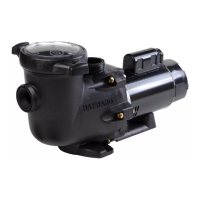
PARTS LISTING
1
2
3
4
5
6
7
8a
8b
9
10
11
12
13a
13b
13c
13d
14
15
16
17
18
19
20
21
22
23
24
Ref No. Part# Description No. Required
SP5700DL
SP2700Z4
SP2700M
SP5700A
SP1495Z1
SP2700Z3
SP5700B
SP1591E
SP1591F
SP5500H
SP1250XZ2C
SP5700E
6060Z1
SP1509Z1UF
SP1509Z2UF
SP1514Z1UF
SP1514Z2UF
SP5700AM
SP2700Z3
SP5700C
SP1500T2
EC1325R
SP1550WA5C
SP5700G
SP5700H
SP2700Z2
SP5700Z4
SP5700Z5
Strainer Cover Assy
Strainer O-ring
Strainer Basket
Pump Housing
O-ring
Screw
Diffuser
1 HP Impeller
1.5 HP Impeller
O-ring
Shaft Seal
Seal Plate
Screw
1 HP Motor
1 HP 2 SP Motor
1.5 HP Motor
1.5 HP 2SP Motor
Motor Housing
Screw
End Bell
Screw
Swtch
Cord Set
Motor Support
Main Base
Housing Square Nut
Bolt
Washer
1
1
1
1
1
2
1
1
1
1
1
1
6
1
1
1
1
1
4
1
2
1
1
1
1
2
2
2
www.haywardcanada.com
SHAFT SEAL CHANGE INSTRUCTIONS
IMPORTANT SAFETY INSTRUCTIONS
PLEASE READ AND FOLLOW ALL INSTRUCTIONS
Shut o water ow to pump by closing appropriate valves or by plugging
both the skimmer outlet port and return port to pool. Disconnect piping or
hoses from the motor/pump assembly.
Remove 2 endbell cover screws and remove endbell cover. Remove white
and red leads. Remove ground screw and ground wire(green).
Remove front base bolt and washer located on the underside of the pump.
Remove front base attachment.
Remove the 4 motor cover screws and slide o motor cover.
Remove the 6 strainer cover housing screws and remove strainer housing.
Remove the 2 diuser screws and diuser.
Hold the motor shaft securely by either inserting a screwdriver in slot at
end of shaft or by using an open-end wrench to engage the at surfaces
provided near end of motor shaft. Rotate the impeller in a counterclock-
wise direction and remove it from motor shaft.
Note how the steel spring section of the old seal is positioned on impeller
hub and remove it by pulling from the impeller.
Loosen the 4 motor through bolts from the back of motor and remove
pump motor plate.
Remove the ceramic stationary portion of the old seal by pressing the
white ceramic seat out of the pump housing recess. If assembly is right, tap
lightly from the “motor” side.
Clean and lubricate the impeller stem and the pump housing recess with a
dilute solution of non-granulated liquid-type soap. Do not use petroleum
or silicone lubricants as these can contribute to seal leakage.
OPTIONAL ELECTRONIC TIMER MODULE INSTRUCTIONS
Your integrated timer module is designed to be programmed to your ltration need, with four (4) possible settings.
TO SET TIMER
1. Move switch “OFF” to “PROGRAM” back to “OFF” - resulting single
tone indicates Setting #1. Repeat until number of tones heard
equals setting desired. ie 3 rapid tones is Setting #3
2. Move switch from “OFF” to “RUN: to begin selected program setting.
SINGLE SPEED MOTOR SETTINGS
Setting 1 - Pump runs 24 hours Continuous ( single tone )
Setting 2 - Pump runs 18 hours, o 6 hours ( 2 tones )
Setting 3 - Pump runs 12 hours, o 12 hours ( 3 tones )
Setting 4 - Pump runs 6 hours, o 18 hours ( 4 tones )
TWO SPEED MOTOR SETTINGS
Setting 1 - Pump runs 24 hours on Hi Speed ( single tone )
Setting 2 - Pump runs 18 hours on Hi, 6 hours on Low ( 2 tones )
Setting 3 - Pump runs 12 hours on Hi, 12 hours on Low ( 3 tones )
Setting 4 - Pump runs 6 hours on Hi, 18 hours on Low ( 4 tones )
TO OVERIDE TIMER SETTINGS
Move switch from “RUN” to “OFF” and back to “RUN” within 3 seconds.
The pump will run for 1 hour and then return to the previous
programmed setting.
If a power failure occurs the timer automatically returns to the
programmed setting.
When servicing electrical equipment, basic safety precautions should always be observed including the following. Failure to follow instruc-
tions may result in injury.
A. WARNING - To reduce the risk of injury, do not permit children to use this product.
B. Disconnect all electrical power service to pump before beginning shaft seal replacement.
C. Only qualied personnel should attempt rotary seal replacement. Contact your local authorized Hayward Dealer or service center if you
have any questions.
D. The National Electrical Code requires either a three (3) foot maximum twist-lock cord set with a GFCI protected receptacle or hard wire
(conduit) connection for swimming pool pump installation. Do not use extension cords.
SAVE THESE INSTRUCTIONS
Exercise extreme care in handling both the rotating and stationary sections of the two-part replacement seal. Foreign matter or improper
handling will easily scratch the graphite and ceramic sealing surfaces.
Press the new rotating portion of the seal assembly onto the impeller stem
with the polished black graphite surface facing away from the impeller.
Carefully press the stationary ceramic potion of the seal into the recess of
the pump shroud, with the polished at surface facing out.
Carefully insert the motor shaft through the pump motor plate and align
with white ceramic stationary seal assembly in place and secure the four
motor through bolts removed in step # 9. Be sure pump motor plate is
positioned properly. Alternately tighten the motor through bolts until the
motor plate is secure. Make certain motor shaft turns freely before
proceeding.
Screw the impeller (clockwise) with the rotating portion of seal in place
onto the motor shaft. Hand-tighten the impeller in place.
Clean (replace if necessary) the O-ring. Assemble the strainer
assembly to the motor plate using the 6 screws removed in step # 5.
Tighten screws alternately and evenly.
Re-assemble motor cover by sliding on cover and installing 4 screws
removed in Step # 4.
Replace front base attachment and screw in nut and washer removed in
Step # 3.
Reconnect wire leads from endbell assembly. White lead on L2 and red lead
on L1. Replace ground wire and screw removed in Step # 2. Ensure leads
and ground screw are rmly attached.
Align endbell cover with the two inside motor bosses and tighten endbell
cover screws.
Reconnect pump into the piping or hoses provided. Open all valves and
make sure that the pump strainer housing is full of water before restarting
the pump.
1.
2.
3.
4.
5.
6.
7.
8.
9.
10.
11.
12.
13.
14.
15.
16.
17.
18.
19.
20.
21.
IS 5700 HC-08
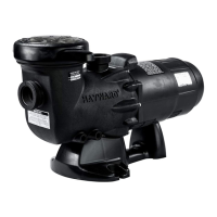
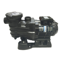
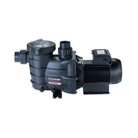
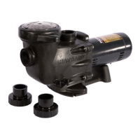
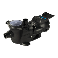
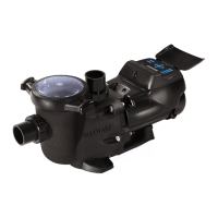
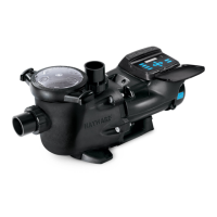
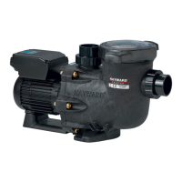
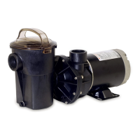
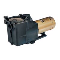
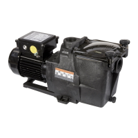
HAYWARD Hi-Performance SELF-PRIMING PUMPS
INSTALLATION AND OPERATING INSTRUCTIONS
Your Hayward Turbo Flo II pump has been quality and
engineered to give you many years of ecient, dependable
service. The non-conductive, corrosion-proof motor housing
provides protection from the elements and insulates the
electrical motor parts from outside contact.
The advanced design reduced operation and maintenance to
simple, common-sense procedures.
GENERAL TIPS ON PUMP INSTALLATION
For best pump performance, locate the system below the pool
water line and as close to the pool as possible. If you own an
above ground pool please see Note: NSPI-4 Article V, for safe and
proper installation of the equipment package. Make sure
suction joints are tight. Suction pipe should be as large or larger
than discharge pipe.
Damp, non-ventilated locations should be avoided. Motors
require free circulation of air to aid in cooling.
Insure that the electrical supply available agrees with the
motor's voltage, phase and cycle, and that wire size is adequate
for the HP/KW rating and distance from the power source. Motor
must always be properly grounded. If cord connected, use only
a properly grounded outlet. Electrical circuits should be
protected by proper size ground fault circuit interrupter (GFCI).
All electrical wiring should be performed by qualied personnel
and must conform to local codes and regulations.
STARTING AND PRIMING INSTRUCTIONS
Fill strainer/housing completely with water. Never operate the
pump without water. Water acts as a coolant and lubricant for
the mechanical shaft seal.
Open all suction and discharge lines and valves, as well as air
bleed (if available) on lter. (The air that is to be displaced from
the suction line must have some place to go).
Turn on power and allow a reasonable time for priming. Priming
time depends on suction lift and length of suction piping. If
pump will not start, or will not prime, see TROUBLE SHOOTING
GUIDE on back page.
Note: NSPI-4 Article V, standard for above ground and on
ground pools, advises that components such as the ltration
system, pumps and heater be positioned so as to prevent their
being used as a means of access to the pool by young children.
MAINTENANCE
Clean strainer basket regularly. Do not strike basket to clean.
Inspect strainer cover gasket regularly and replace as necessary.
Hayward pumps have self-lubricating motor bearings and shaft
seals. No lubrication is necessary.
Keep motor housing clean. Insure air vents are free from
obstructions, debris, etc.
4. Occasionally, shaft seals must be replaced, due to wear or
damage. See instructions
STORAGE/WINTERIZING
Pump and motor must be protected from freezing. Shut o all
electric power. Disconnect cord/electrical connections and
plumbing connections. Drain thoroughly and clean out any
debris. Store pump and motor in a dry, well ventilated room.
1.
2.
3.
® Hayward Pool Products Canada, Inc. -- Licensee
www.haywardcanada.com
Turbo Flo II
MANUFACTURED EXCLUSIVELY BY HAYWARD
2880 PLYMOUTH DRIVE, OAKVILLE, ONTARIO L6H 5R4 1-888-238-POOL