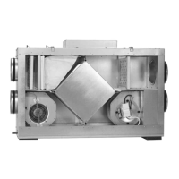
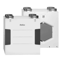
Heat recovery unit KWLC 350
1
I
t is important for safety reasons, that you read and observe these instruc-
tions fully before proceeding.
RECEIPT
T
he consignment contains one of the following units including a three speed con-
troller and a summer-heat exchanger:
KWLC 350 __ __ __
S vertical installation
L horizontal installation
EH electric heater battery
WW water heater battery
Please check delivery immediately on receipt for accuracy or damage, please no-
tifiy carrier immediately of any damage. In case of delayed notification, any possi-
ble claim may be void.
STORAGE
When storing for a prolonged time the following steps are to be taken to avoid da-
maging influences: protection by dry air and dustproof packing (plastic bags with
drying agent and moisture indicators). The storage area must be free of water, vi-
bration and temperature variations.
When storing for years or non rotation of motor an inspection of the bearings with
possible replacement and an installation inspection in accordance with VDE 0530
are necessary before starting using the unit. Damage caused by incorrect storage,
transportation or installation are not valid warranty claims.
OPERATION / USE
The unit is designed to ventilate a combination of living rooms, bathrooms and kit-
chens in a single dwelling. The unit is equipped with a heat recovery cube. It must
not be connected to kitchen hoods or laboratory extract systems. The standard
equipment has a working temperature range from -20°C up to 40°C. The ambient
temperature where the unit is installed must not be below 0°C. For operation un-
der unusual conditions, e.g. high humidity, long periods of standstill, high air pollu-
tion, extreem climatic conditions (e.g. operating temperature over 40°C), technical
or electronic inputs other than standard operation may affect the units performan-
ce. For this reason please enquire and obtain a quotation for a suitable unit, if avai-
lable.
UNIT OPERATION
In the heat exchanger the cold outside air and the warm extracted air “cross over”
and the temperature of the incoming air is raised. Through this method up to 80%
of the energy of the warm air is tranfered to the incoming air (Pic. 3). In addition a
thermostatically controlled heating element warms up the inlet air, in extreme cold
weather conditions, to the required temperature. Frost coditions are detected by a
Thermo-Humidity sensor which is positioned in the heat exchanger. The after heater
warms up the inlet air and the pre heating element is used as an additional heater to
avoid frost in the heat exchanger. The inlet air is directed to the living rooms and be-
drooms through ducts and dampers. The stale air is extracted from the bathrooms,
toilets and kitchens and flows back to the heat exchanger via the ducting system
and fan, transfering heat before being discharge into the open air.
PERFORMANCE DATA
To achieve the given performance, the unit must be correctly installed. The duct
system must be designed to be within the units pressure capablities and have
good flow into and out of the unit otherwise there will be a reduction in the units
performance. Noise figures are stated as sound power levels L
W
A
in dB(A) (confor-
m
ing to DIN 45635 Pt.1). Sound pressure levels L
PA
d
epend on room specific con-
ditions.
INSTALLATION-ASSEMBLY (picture. 3, page 4)
The KWLC 350 S is suitable for "vertical" installation wherever desired usually in the
l
oft space. As a base to mount the unit on we recommend chipboard on a secure
mineral wool board (approx. 60 x 120 cm) to prevent vibration transmission or use a
c
ommercial anti vibration pad (approx. 60 x 120 cm). The mounting surface must
be level, flat and even. The KWLC 350 L is suitable for "horizontal" installation. For
e
ffective condensate removal from the unit, the unit should slope down in the
direction of the drain pipe by 5° the init has differing height feet to acheive
t
his . The ducting should be as short as possible and tight bends should be avoided
as they can lead to a high pressure loss and airflow noise. The ductwork joints
s
hould be fully sealed to prevent air loss. The supply and extract ducting should be
insulated to gain the best thermal efficiency. For maintenance and installation work,
i
nstal the unit in an accessible position. When installed in areas with low ambient
temperature (e.g. roof space) the unit may require additional insulation.
The summer-heat exchanger and operating switch are supplied inside the
unit, these must be removed before installation. It is essential that the instal-
led unit tray has a drop in the direction of the condensate water flow.
G
eneral recommendation
The use of oil or gas burning devices e.g. boilers, gas heaters gas hobs and ovens
r
equire a free flow of air. Used in combination with a heat recovery unit all national
r
egulations must be followed. A separate air inlet may have to be provided for.
– CONDENSATION RUN-OFF (picture 4/5)
The condensation pipe (4) is to be connected to the water run off by means of a
flexible pipe of 15mm diameter. If it is not in a room which is heated, it must be is-
sulated. A suitable drain trap is to be provided with a minimum height of 100 mm,
otherwise water could be drawn back through the fan.
Fill the drain trap with water before putting into operation to avoid smells
from the drain system. The regulations of the water board and other legislati-
on must be observed.
NOTE: When connecting the condensation pipe by (cold) pressing avoid
any axial or radial forces on the unit drain pipe. The use of a flexible pipe is
recommended.
– AIR DUCTING, VENTILATION CIRCUIT (picture 4.)
When designing the ductwork, try to achieve the shortest possible runs. Use
smooth pipes (rigid plastic or steel ducting), to avoid high pressure loss, noise
etc. For the main ducting (outside air, extract air, inlet air, discharge collection) a
diameter 160 mm or 140 mm is recommened, for side pipes a diameter 80 mm to
125 mm. To reduce condensation in the extract pipes, the ducting has to be insu-
lated where appropriate. Also if inlet and extract ductwork cross unheated rooms
insulation must be provided to reduce heat loss.
Fresh air should be taken into living- and bedrooms, extraction from bathrooms,
toilets and kitchens. To regulate the whole system use adjustable Helios valves.
The extract from the kitchen needs to be filtered. A kitchen hood must not be
connected up to the unit (danger of grease carried into the heat exchanger). There
must be a good air flow (e.g. using door grilles) within the building between intake
rooms and extract rooms.
Important: all fire protection regulations - where applicable- must be follo-
wed.
– Thermo-humidity sensor (picture 5)
The electronic thermo humidity sensor (3) is in the heat exchanger in order to de-
tect the humidity level of the fresh and extract air. This allows a more precise de-
tection of the risk of frost in the heat exchanger.
– ELECTRICAL CONNECTIONS (pic. 5/6)
Electrical connection may only be carried out by a qualified person. All electrical
work must only be carried out with the power supply off. A lockable isolator is re-
quired isolate from the mains with a minimum of 3 mm contact opening of each
pole.
All relevant safety and installation regulations (for example DIN VDE 0100
and IEE regulations) are to be adhered.
Electrical connections are to be made according to wiring diagrams provided in
these instructions. The connection to the control panel are of plug in type using
the cables provided. The unit is designed for continous running and cannot be
switched off as a standard. To switch off please use mount a switch in the supply.