29
voltage between 11 V and 32 V – e.g. if an OEM
amplier is used as signal source – all four in-
ternal jumpers has to be repositioned to the
extended adjustment range (Highlevel 8 - 32
Volts; RCA / Cinch 2 - 8 Volts).
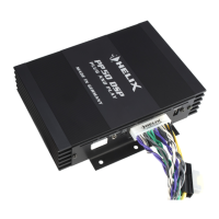
To get access to the jumpers the device has to
be opened. Therefore dismantle the side panel
where the USB input is located by removing the
two Phillips and two Allen screws and pull out
the bottom plate sideways.
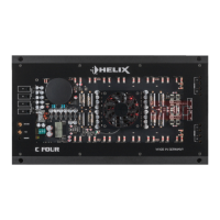
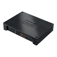
Now you have access to the jumpers of the
channels G to L (J 1 & J 2).
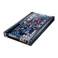
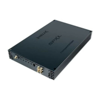
The jumpers of the channels A to F are locat-
ed underneath the highlevel expansion board.
To get access to the jumpers follow the subse-
quent steps:
1. Untighten the two Allen screws.
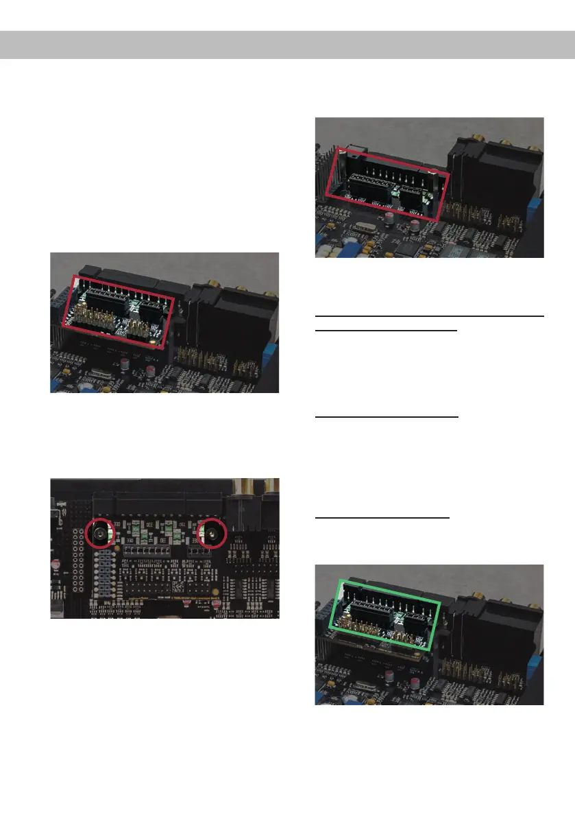
2. Pull the board upwards. Now you have ac-
cess to the jumpers of the channels A to F
(J 3 & J 4).
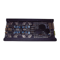
For repositioning a jumper simply pull it up-
wards and plug it to the desired plug position.
Make sure that the jumper is reinserted properly
and all pins are fully inserted.
If you are not sure regarding the signal sources
output voltage, please contact your HELIX spe-
cialist dealer.
Overview plug-in positions:
Jumper 1 (J 1): Channel G - J
Jumper 2 (J 2): Channel K - L
Jumper 3 (J 3): Channel A - D
Jumper 4 (J 4): Channel E - F
Ex factory jumper positions:
Value range: Highlevel 4 - 16 Volts
RCA / Cinch 1 - 4 Volts
J 1
J 2
J 3
J 4
J 1
J 2
 Loading...