3
ATTENTION !
If a power cord gets damaged it should be substituted with new one.
For specific installation schemes with the description of connecting devices to the controller, see section 4 (Installation schemes).
3. Switching on and using the controller
3.1 First switch on of the controller
Upon connecting the controller to a power source it will be switched on in the stand-by mode and a diode will get lit. In this mode the LCD display gets slightly back-lit and the current
controller software version appears on the screen. When the controller is in the stand-by mode you can switch it off with the button. During regular controller operation it is always
possible to get it back into the stand-by mode by pressing the button. In the standby mode all the inputs and sound alarms are switched off. Full description of the messages
displayed on the controller screen has been presented in Figure 2.
ATTENTION ! The controller has a system password 0110 to secure its functions against unauthorised persons and children.
With the first switch on of the controller in a regular operation mode the keyboard and temperature sensors will get calibrated. During calibration it is strictly prohibited
to touch the controller keyboard as it may result in abnormal controller operation.
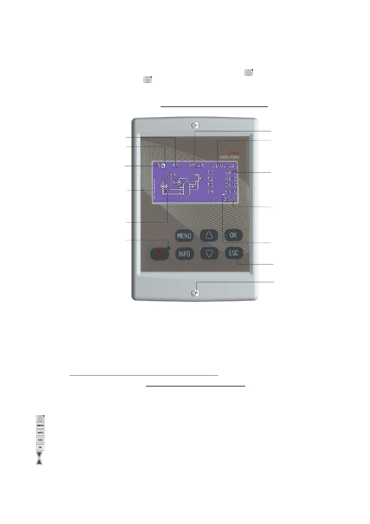
Fig. 2. Description of the basic screen on the LCD display
ATTENTION !
Remember to install temp. sensors correctly as described in the selected scheme. Change in sensor location might result in irregular operation of the control system.
Insulate the points where sensors are connected with additional wires or insulate all blocks connecting sensors with wires.
When the collector pump is switched off or the T3 sensor on collector return is disconnected, dashes appear on the display in place of instantaneous power of the solar
collectors (- - - - -). The power calculation option is unavailable for the schemes no 10, 12, 15 and 16.
When the controller is in regular operation and during the blanking period no key is pressed, the LCD screen will be switched off. After pressing any key on the keyboard
the LCD back light will switch on for the blanking period set. Screen blanking aims at limiting energy consumption.
Connect the electrical plug to the socket equipped with a protective terminal and protected with RCD.
It is forbidden to install pump units in close vicinity of open flames, high temperatures and storage of flammable materials.
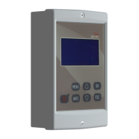
3.2 Controller keyboard description.
The controller has a touch keyboard with 7 keys which call the following functions:
- switching the controller on into regular operation or switching it off into the stand-by mode.
- entry into the controller MENU from the main screen level
- contact data
- cancelling all the controller operations or return to the previous screen
- confirming all the controller operations or moving to the next screen
- selection of all the controller options (down) or change (reduction) of all the values available for the controller
- selection of all the controller options (up) or change (increase) of all the values available for the controller
ATTENTION ! Excessive dirt on the display and the keyboard might result in irregular key operation.
3.3 Controller operation
Pump rotation, Range 1-15
(only when the solar panel
pump is on)
pompie kolektorowej)
Number of the selected installation scheme
Installation schematic diagram
with working devices animated
z
Current date (dd : mm : yy)
Current time
LED indicating that the controller
is connected to the mains
Touch buttons
Screws holding the front panel.
Under the display there are connection
terminals for temperature sensors and
electrical devices.
Antilegionella function switched on
Continuous light function enabled
Readings of temperature sensors T1
T6 as well as
of the instantaneous power of additional device (Pe)
and the additional flow rate value of flowmeter (Fe).
Err Damage or lack of a sensor needed in the
selected installation scheme (except T5)
- - - Damage or lack of a sensor not needed in the
selected installation scheme.
The following values are displayed when the
pump is in operation:
-
Instantaneous collector power
- Current heat carrier flow
- Pump power consumption(If pump is switched
off “- - - - -“ is displayed).
Information on the existence of additional
readings (“down arrow” key):
temp. T5, T6, flow 2 (Fe), power 2 (Pe)
return from readings (“up arrow” key).
 Loading...