INSTALLATION GUIDE
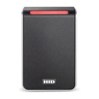
iCLASS SE® Express R10 Reader
13.56 MHz / 2.4 GHz Contactless
PLT-03681, Rev. A.2
This Installation Guide is for informational purposes only. HID makes no warranties, expressed or implied, in this summary. Company, product names and data used in sample output
are fictitious. Specifications are subject to change without notice.
© 2018 HID Global Corporation/ASSA ABLOY AB. All rights reserved. This document may not be reproduced, disseminated or republished in any form without the prior written
permission of HID Global Corporation. HID GLOBAL, HID, the HID Brick logo, the Chain Design, HID Reader Manager, HID Mobile Access, and iCLASS SE are trademarks or registered
trademarks of HID Global, ASSA ABLOY AB, or its aliate(s) in the US and other countries and may not be used without permission. All other trademarks, service marks, and
product or service names are trademarks or registered trademarks of their respective owners.
hidglobal.com
An ASSA ABLOY Group brand
Supplied parts
iCLASS SE Express R10 Reader (1)
Installation Guide (1)
0.138-20 x 1.5" self tapping screws (2) – for installing
the reader directly to a wall
0.138-32 x 0.375" screws (3) – for mounting to an
enclosure with Imperial (US) threads (2) and attaching
the reader to the back plate (1)
M3.5 x 12mm screws (2) – for mounting to an enclosure
with Metric (EU etc) threads
0.138-32 x 0.375" security screw (1) – alternative
security screw for attaching the reader to the back
plate
Recommended parts (not supplied)
Cable, 5-9 conductor (Wiegand or Clock-and-Data)
Certified LPS DC power supply
Security tool HID 04-0001-03 (for anti-tamper screw)
Drill with various bits for mounting hardware
Mounting hardware
Reader spacer (PN: 6132AKB) when mounting on or
near metal or metal junction boxes - see How to Order
Guide
IP65 Mounting gasket (PN: IP65GSKT-R10, 10 pcs per
kit), recommended for outdoor installation
Specifications
INPUT VOLTAGE (VDC) 12 VDC
CURRENT
STANDBY AVG
1
46 mA
MAX AVG
2
60 mA
PEAK
3
250 mA
OPERATING TEMPERATURE -30° F to 150° F (-35° C to 66° C)
CABLE LENGTH
4
Communication Lines (Wiegand)
22 AWG: 500 ft (152 m)
REGULATORY REF NUMBER R10FKNN
FREQUENCY BLE: 2.4 - 2.480 GHz
HF: 13.56 MHz
FCC & IC IDS FCC-ID: JQ6-iCLASSR10F
IC-ID: 2236B-ICLASSR10F
1
Standby AVG - RMS current draw without a card in the RF field.
2
Maximum AVG - RMS current draw during continuous card reads. Not evaluated by UL.
3
Peak - highest instantaneous current draw during RF communication.
4
Wiegand Cable Lengths: 500 ft (152 m) 22 AWG @ STANDBY AVG 46 mA, MAX AVG 62.5 mA, PEAK 250 mA
Optional Features
Optical Tamper enabled by default – Once activated, when the mounting plate is removed, the optical tamper will
open the circuit between Tamper#1 and Tamper#2 reader control lines. Tamper#1 and Tamper#2 control lines are
interchangeable. Either of these lines can be connected with the reader ground line to reduce the number of cable cores
required in the reader cable. Tamper#1 and Tamper#2 are rated 0-12VDC at 100mA.
Configuration Cards – The reader can be modified to meet the specific requirements of an installation. Configuration
options include; audio visual, and CSN outputs. See the HID Reader Manager™ solution on www.hidglobal.com for further
details.