_____________________________________________________________________________________________________
__________________________________________________________________________________________________________________________________________________________________________________________________________
_____________________________________________________________________________________________________
HID Corporation 9292 Jeronimo Road Irvine, CA 92618-1905 USA TEL (949) 598-1600 (800) 237-7769 FAX (949) 598-1690
Web page, E-mail - www.hidcorp.com - ProxPoint Installation Manual 6005B-910 Rev A Page 2 of 2
PARTS LIST (Included)
PARTS LIST (Included)PARTS LIST (Included)
PARTS LIST (Included)
Quantity
QuantityQuantity
Quantity
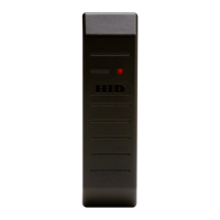
- ProxPoint Plus
TM
Reader with snap-on
cover and 18” cable
1
- #4-24 x 1” self-tapping flathead screw 2
- Installation manual 1
PARTS LIST (Not
PARTS LIST (NotPARTS LIST (Not
PARTS LIST (Not-
--
-Included)
Included)Included)
Included)
Quantity
QuantityQuantity
Quantity
- Wire splice 9
- DC Power supply 5.0 VDC or 12 VDC 2
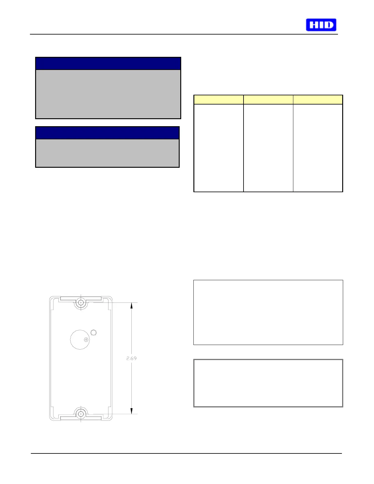
Mounting Instructions
Mounting InstructionsMounting Instructions
Mounting Instructions
• Determine an appropriate mounting location. The
reader may be mounted to any surface, including
metal.
• Drill two (2) 5/64-inch (2mm) holes approximately 1
inch deep for mounting the reader.
• Drill a 5/8-inch (16mm) hole for the cable.
• Remove the snap-on cover from the reader and
secure the reader to the mounting surface.
• Route the cable from the reader and/or power
supply to the host. A linear type power supply is
recommended. Check all electrical codes for proper
cable installation.
• Test the operation of the reader. After completion of
the test, replace the snap-on cover.
Connecting the Reader to the Host
Connecting the Reader to the HostConnecting the Reader to the Host
Connecting the Reader to the Host
Connect the reader to the host according to the wiring
table below and the host installation guide.
Wiegand Clock & Data Wire Color
+DC +DC Red
Ground Ground Black
--- Card Present Violet
Data0 Data Green
Data1 Clock White
Shield Ground Shield Ground Drain
Green LED Green LED Orange
Red LED Red LED Brown
Beeper Beeper Yellow
Hold Hold Blue
Testing and Operation
Testing and OperationTesting and Operation
Testing and Operation
• When power is applied to the reader the LED will
flash green three (3) times while the beeper beeps
simultaneously. The LED will then turn red. This
indicates that the microcontroller is operating
properly.
• Present an ID card to the reader. The LED will
momentarily turn green while the beeper beeps
once, indicating that the card was read successfully.
Important Product Specifications
Important Product SpecificationsImportant Product Specifications
Important Product Specifications
Power requirements (linear supply)
Power requirements (linear supply)Power requirements (linear supply)
Power requirements (linear supply)
Operating Voltage Range 5.0 – 16.0 VDC
Absolute Maximum Voltage 18 VDC
Peak Current 80 Ma
Average Current 5V or 12V 20 Ma
Maximum cable distance 500 ft (153 m)
To host
FCC Compliance Statement:
FCC Compliance Statement:FCC Compliance Statement:
FCC Compliance Statement:
This device complies
with part 15 of the FCC rules. Operation is subject to
the following two conditions: (1) this device may not
cause harmful interference, and (2) this device must
accept any interference received, including
interference that may cause undesired operation.

 Loading...