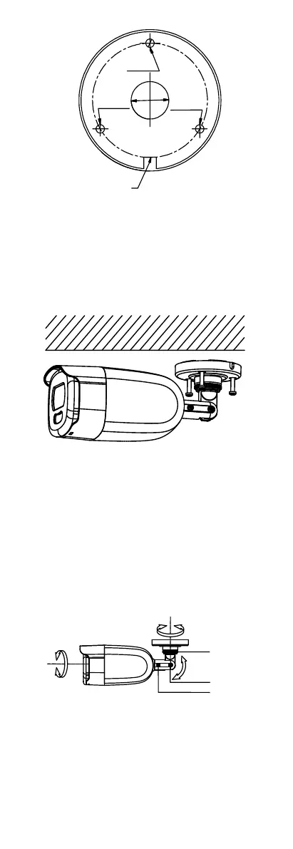
Figure 2-8 Drill Template
Note:
Drill the cable hole in the center of the drill template,
when adopting ceiling outlet to route the cable.
3. Route the cables through the cable hole (optional)
or the side opening.
4. Fix the camera to the ceiling with supplied screws.
Figure 2-9 Fix the Camera to the Ceiling
Note:
The supplied screw package contains self-tapping
screws, and expansion bolts.
For cement wall/ceiling, expansion bolts are
required to fix the camera. For wooden
wall/ceiling, self-tapping screws are required.
5. Connect the corresponding power cord, and video
cable.
6. Power on the camera to check whether the image
on the monitor is gotten from the optimum angle. If
not, adjust the surveillance angle.
Figure 2-10 3-Axis Adjustment
1) Loosen the No.1 adjusting screw to adjust the pan
position [0° to 360°]. Tighten the No.1 adjusting
screw.
2) Loosen the No.2 adjusting screw to adjust the
tilting position [0° to 180°]. Tighten the No. 2
adjusting screw.
 Loading...