Note:
The supplied screw package contains self-tapping
screws, and expansion bolts.
For cement wall/ceiling, expansion bolts are
required to fix the camera. For wooden
wall/ceiling, self-tapping screws are required.
5. Connect the corresponding power cord and video
cable.
6. Power on the camera to check whether the image
on the monitor is gotten from the optimum angle. If
not, adjust the camera according to the figure below
to get an optimum angle.
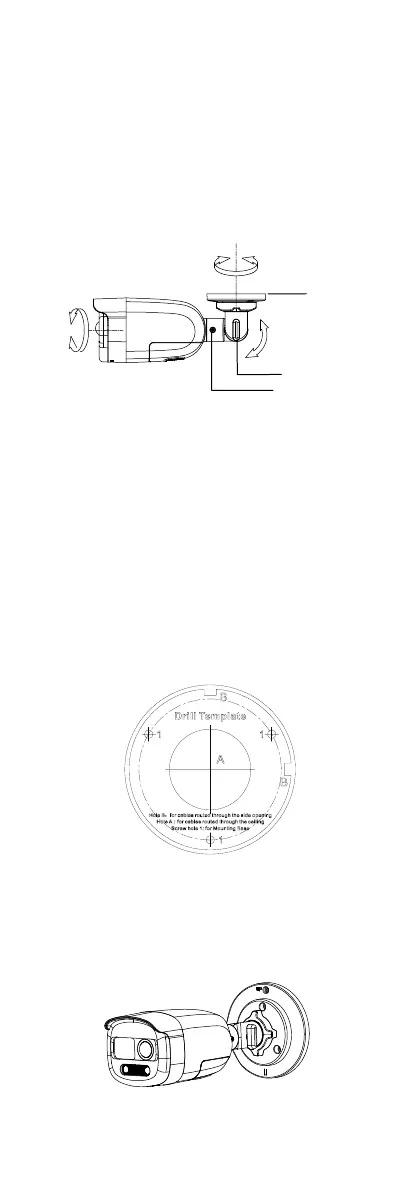
Figure 2-3 3-Axis Adjustment
1). Loosen the trim ring to adjust the pan position
[0° to 360°].
2). Loosen screw A to adjust the tilt position [0° to
180°].
3). Loosen screw B to adjust the rotation position [0°
to 360°].
2.1.2 Ceiling/Wall Mounting with Junction Box
Before you start:
You need to purchase a junction box in advance.
Steps:
1. Paste the drill template on the ceiling/wall.
2. Drill screw holes and the cable hole on the ceiling
according to the drill template.
Figure 2-4 Drill Template of Junction Box
3. Take apart the junction box, and align the screw
holes of the camera with those on the junction
box’s cover.
4. Attach the camera on the junction box’s cover with
supplied screws.
Figure 2-5 Attach the Camera on the Junction Box’s
Cover
 Loading...