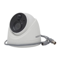
Figure 2-3 Fix the the Camera
6.Adjust the camera according to the figure below
to get an optimum angle.
Figure 2-4 3-axis Adjustment
0 ~360°°
0~75°°
0 ~360°°
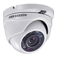
2.2 Installation of Type CameraII
1.Drill the screw holes and the cable hole on the
ceiling according to the supplied drill template.
Steps:
Figure 2-5 The Drill Template
Figure 2-6 Fix the Mounting Base and Camera
2.Fix the mounting base to the ceiling with the
supplied screws.
3.Route the cables to the cable hole and connect
corresponding power cable and video cable.
4.Secure the camera to the mounting base.
5.Fix the enclosure to camera.
6.Attach the trim ring to the camera and rotate
it clockwise to secure the camera loosely.
0 ~360°°
0~75°°
0 ~360°°
Figure 2-7 3-axis Adjustment
2.3 Installation of Type CameraIII
Clip Plate
1.Drill the screw holes and the cable hole on the
ceiling according to the supplied drill template.
Steps:
Figure 2-8 The Drill Template
Figure 2-9 Fix the Mounting Base and Camera
2.Fix the mounting base to the ceiling with the
supplied screws.
3.Route the cables to the cable hole and connect
corresponding power cable and video cable.
4.Secure the camera to the mounting base.
5.
Adjust the camera according to the figure below
to get an optimum angle.
0~360°°
0~75°°
0 ~360°°
Figure 2-10 3-axis Adjustment
Screw Hole
Cable Hole
Screw Hole
Cable Hole
7.Adjust the camera according to the figure 2-7 to
get an optimum angle and tighten the trim ring.
3.2.2 WB
3.2.1 AE
Move the cursor to AE, and you can adjust the
image brightness by the ,BRIGHTNESS EXPOSURE
MODE AGC, and .
:Brightness
Brightness refers to the brightness of the image.
Exposure Mode:
Move the cursor to , you can selectExposure Mode
the exposure mode between and .Globe BLC
When BLC is selected as the exposure mode, the
level of BLC mode can be adjusted, as shown in the
Figure 3-2.
3.2.4 VIDEO SETTING
Contrast:
Contrast enhances the difference in color and light
between parts of an image.
You can set the value from 1 to .
10
Sharpness:
Sharpness determines the amount of
detail that an imaging system can reproduce.
You can set the value from 1 to 10.
Saturation:
You can set the saturation level of the image. The
value is from 0 to 10.
DNR:
DNR decreases the noise effect, especially in low
light conditions and delivers more accurate and
sharp image quality. You can set the value from
0 to 7.
:Mirror
You can set the Mirror status as H, V, HV, or OFF.
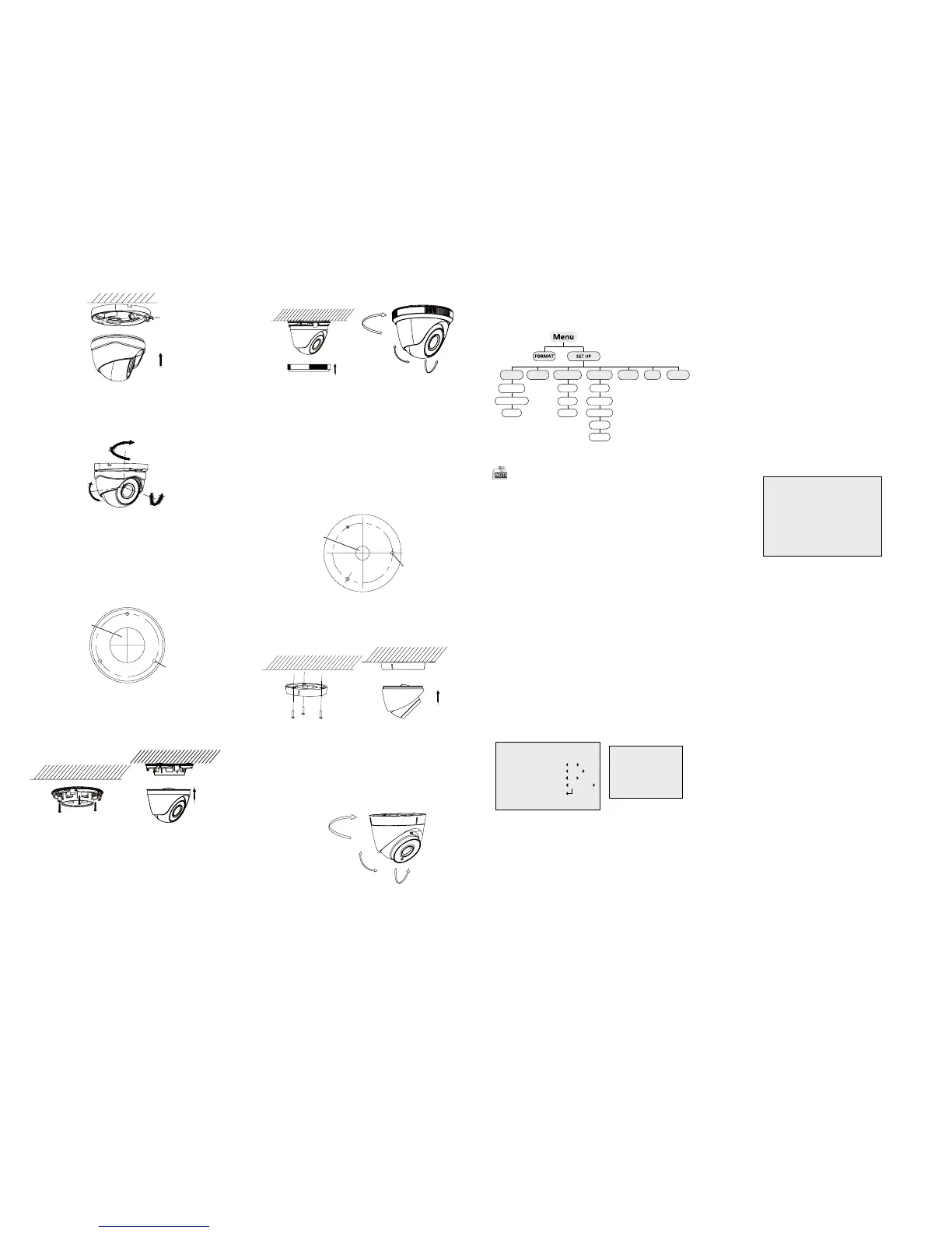
3 Menu Operation
Figure 3-1 Main Menu
VIDEO
SETTING
DAY/NIGHT
WB
RESET
BRIGHTNESS
MODE
INFRARED
SMART IR
CONTRAST
SHARPNESS
SATURATION
EXIT
AE
DNR
MIRROR
EXPOSURE MODE
AGC
SAVE/EXIT
With a coaxial camera controller (purchase
separately) or calling the preset No.95 you can
select the menu and adjust the camera parameters.
3.1 FORMAT
You can set the format as PAL/NTSC.
3.2 SET UP
Move the cursor to , and press menu buttonSET UP
to enter the SET U P sub menu.
EXPOSURE
1.BRIGHTNESS
2.EXPOSURE MODE
LEVEL
3.AGC
4.RETURN
5
BLC
5
MIDDLE
Move the cursor to WB, and you can set White
Balance mode as and in this menuAWB MWB .
AWB: white balance is being adjusted
automatically.
: Set the value from 1 to 10.MWB R GAIN/B GAIN
As shown in Figure 3-3.
WB
MODE MWB
R GIAN 1-|--10
B GAIN 1-|--10
RETURN 8
AGC:
AGC optimizes the clarity of image in poor light
scene. AGC level can be set as OFF, LOW, MIDDLE
and HIGH.
Figure 3-2 EXPOSURE
Figure 3-3 WB
Figure 3-4 DAY/NIGHT
3.2.3 DAY & NIGHT
Move the cursor to DAY & NIGHT, and select
COLOR B/W SMART, , or as the DAY & NIGHT mode.
COLOR: The image is colored in day mode all the
time.
: The image is black & white all the time, andB/W
the IR LED turns on in the low-light conditions.
: Select to turn on/off the INFRARED_LAMPSMART
and to set the Smart IR level from 1to 16.
As shown in Figure 3-4.
DAY/NIGHT
MODE SMART
INFRARED OFF
SMART IR 0-|--5
RETURN 8
3.2.7 SAVE/EXIT
3.2.5 Reset
Reset all the settings to the default.
3.2.6 EXIT
Exit and Save & exit are selectable.
Move the cursor to , and press OK toSAVE & Exit
save the settings and exit the menu.
 Loading...