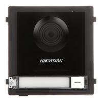
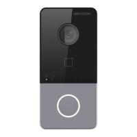
DS-KB2411T-IM
Doorphone
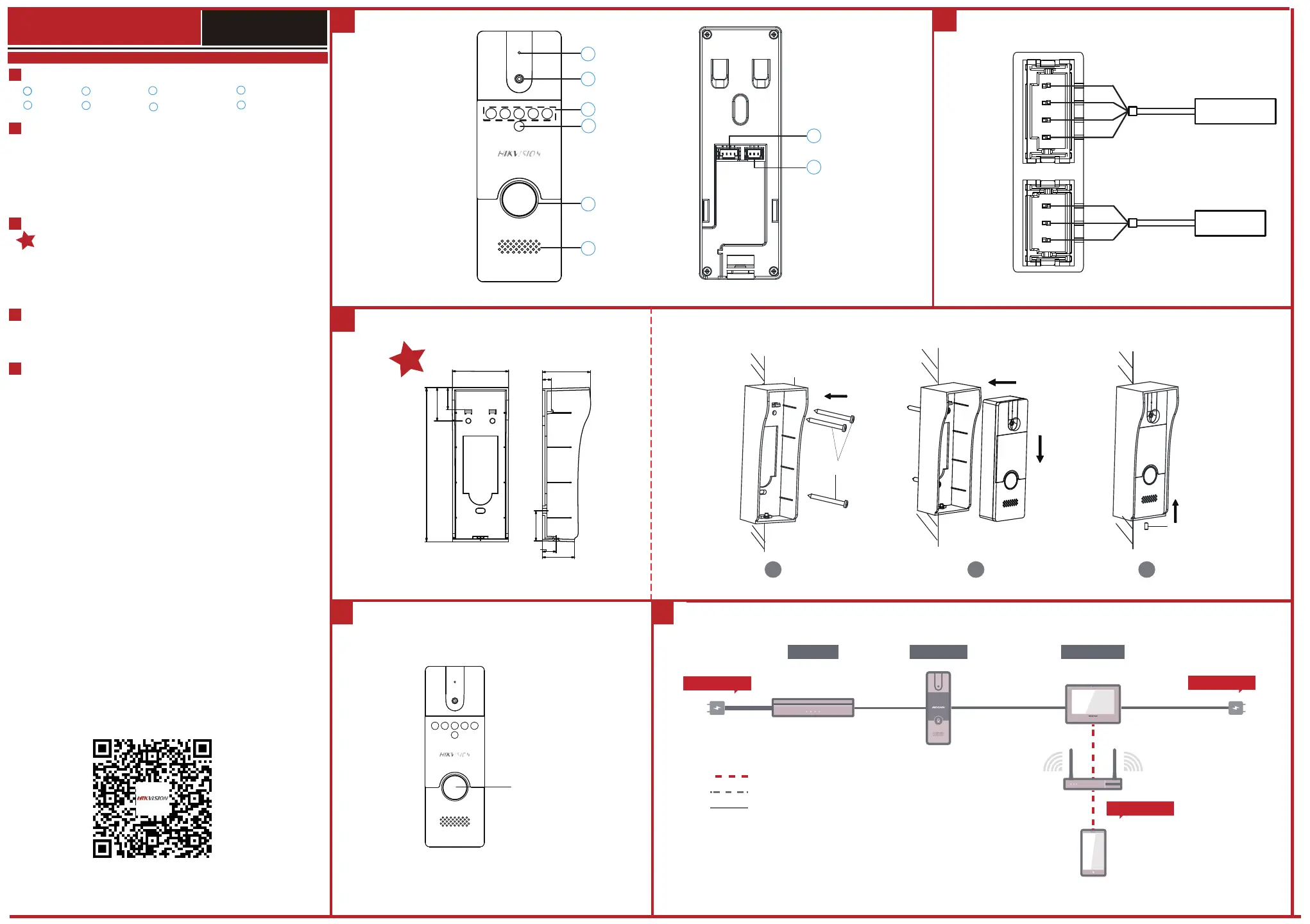
Microphone
2
IR Supplement Light
3
Photoresistor
4
Call Button
5
Loud speaker
6
Four-Wire Interface
7
Lock Interface
8
Terminal and Wiring
2
Installa�on
3
Diagram References
1
Appearance
Steps:
1.
Fix the wall mounting shield to the wall with 3 screws.
2.
Hook the door station to the shield tightly by inserting the hooks of shield panel into
the slots on the rear panel of the door station.
3.
Secure the door station with the mounting shield with the set screw.
1
4
5
1
Local Operation
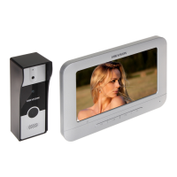
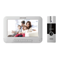
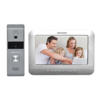
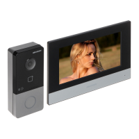
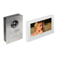
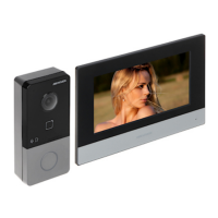
Typical Application
3
1
Built-in Camera
Four-Wire Interface
G: Grounding Signal
A: Audio Input/Output
V: Video Output
B+: Power Supply (from Indoor Station)
Lock Interface
NC: Door Lock Relay Output/Normally Closed
COM: Door Lock Relay Output/Common
NO: Door Lock Relay Output/Normally Open
Wall Moun�ng Shield
Note:
To install the door station, the wall mounting shield is required.
ENGLISH
2
1
2
3
4
5
6
7
8
Indoor Station
Electric Bolt
G
A
V
B+
NC
COM
NO
48.83 mm
134.5 mm
29.08 mm
19.12 mm
7.6 mm
41.78 mm
26.25 mm
28.02 mm
12±0.05 mm
Power Supply
DoorphoneDoor Lock
Wi-Fi/UTP
Internet
APP Control
Indoor Station
Multicore Cable
4-wire
Power Supply
Optional
4 5
Call Button
Press the call button to call the resident.
Note: When press the call button to call the resident, the maximum ring duration of the
indoor station is 30s.
You can connect the door station to indoor station via the four-wire interface.
Screws
Wall Mounting Shield
Set Screw
1
2
3
Up to 2 analog doorphones can be connected to the indoor station with four-wire
cables. Multiple functions, live view and remote door unlocking for example, can be
realized via operations on the indoor station or Hik-Connect App.
Scan the QR code to view the user manual
for detailed informa�on of the kit.
 Loading...