ENGLISH
Diagram References
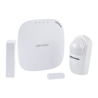
Appearance
Wiring and Installaon
Set up via 4200 Client
Restore Default Sengs
Set up via APP
Add a Camera for the Zone
Configure Video-Push
Log Into the Web Client
1. Download and install the iVMS-4200 client.
Note: Get the client soware from the official website:www.hikvision.com.
2. Enter Device Management page, click “Device - Online Device”, select the device in the
Online Device List, click Edit Network Sengs, change the port as 80, and click Add to Client.
Note: You should acvate the device for the first usage.
Set Up
1
2
3
Set up via Web Client
Input the device IP address in the address bar of the web browser. Create a password to
acvate the device and log into the web client.
Default IP Address when using mobile broswer in the AP mode:192.168.8.1. The device must be in the AP mode.
Default IP Address when connecng the network cable with computer directly :192.0.0.64
AC Power
Power On
System Fault
No Fault
Panel is added to Hik-connect account
Panel is not added to Hik-connect account
Armed
Disarmed
Alarm Occurred
Indicators Components
Device Tampered
No Alarm
Power Off
Status
Link
Arm/Disarm
Alarm
Note: Remove the rear cover, and some of the components and interfaces are on the rear panel.
Reset: Power on the device, the yellow status indicator will flash 3 mes. Hold the reset buon for 5 s to reset
the device.
1
2
2
2
3
5
4
1. Loosen the screw on the top, press the lock nut, and open the case of the control panel.
2. Route the cables, and secure the rear cover in the installaon posion with the supplied
screws.
3. Fix the SIM card module (should be purchased separately) with four plasc bolts.
4. Fix the telephone module (should be purchased separately) with two plasc bolts.
5. Wire the cables.
1. Log into the App Store or Google Play and input Hik-Connect to search and install the
mobile client.
2. Log into the APP with Hik-Connect account.
3. Tap Add Device. Scan the device QR code on the rear panel(on the lable).
4. Tap Connect to a Network. Select Wireless Connecon (AP) as the connecon mode.
5. Push the AP/STA mode switch to the AP posion, tab Confirm.
6. Tap Connect to Wi-Fi on the promt-up window. Select and connect to a stable Wi-Fi , and
click Next.
7. Create a password to acvate the device.
8. Push the AP/STA mode switch to the STA posion.
Note: You need to enter the Verificaon Code (on the device lable which is pasted on the rear panel) before
acvaon if you add the device by entering the device serial No.(SN).
Baery
Connector
Network
Interface
Power
Interface
Lock Nut
AP&STA
Switch
TAMPER
Switch
Wiring
Terminal
2
12
2
13
2
11
Reset
Buon
2
10
2
9
2
8
2
7
2
6
You can view the alarm video via APP and email. For detailed sengs, refer to Security
Control Panel User Manual.
Reboot the device. Boot the device, and hold the reset buon for 5s aer the Fault indictaor
flashes 3 mes. The device will prompt a message to indicates the operaon status.
TAMPER Screw
It is compulsory to secure the TAMPER screw.
Specification
3
2
1 2
21 22
2
5
2
6
2
8
2
7
2
3 24
212
213
2
11
2
10
2827
2
6
2
1 22 23 24 25
29
25 2
8
CAUTION
RISK OF EXPLOSION IF
BATTERY IS REPLACED BY AN
INCORRECT TYPE
DISPOSE OF USED BATTERIES
ACCORDING TO THE
INSTRUCTIONS
CAUTION
SUITABLE FOR MOUNTING ON
CONCRETE OR OTHER
NON-COMBUSTIBLE SURFACE ONLY
APSTA APSTA
1
2
3
4
2
3
......
1
2
3
Power Supply
Network
4
Telephone Module Wiring
AP
STA
AP
STA
Product Informaon
6. Connect the baery to the control panel.
Note: The condion of no SIM card, no baery, AC power off, or network disconnected, will cause Control Panel Fault.
7. Fix the power cables with the cable clip.
8. Close the control panel, and ghten the top screws to complete the installaon.
Alarm Input/Alarm Output/RS-485 Wiring
21
Alarm Input Wiring
22
a.
Alarm Output Wiring
23
RS-485 Wiring: Wireless Receiver, keypad, etc.
NC Detector
b.
c.
NO Detector
Unoccupied Zone
The AP mode is only Supported by device with Wi-Fi funcon.
Hybrid Security Control Panel
1. Click System-Network Camera, and you can add cameras for the control panel.
2. Enter the “Device Management” page, select a zone, and select a camera to link with the zone.
You can also link a camera with the zone via APP, refer to the Security Control Panel User Manual
for details.
The funcon varies depends on the model of device.
Alarm
Lamp
Alarm
Lamp
Alarm
Lamp
Alarm
Lamp
Siren
Keypad
12VDC
Power Adapter
N.C
N.O
2K2
EOL
N.C
N.O
2K2
EOL
N.C
N.O
2K2
EOL
N.C
N.O
2K2
EOL
N.C
N.O
2K2
EOL
N.C
N.O
2K2
EOL
N.C
N.O
2K2
EOL
N.C
N.O
2K2
EOL
Z1 G Z2 Z3 G Z4 Z5 G Z6 Z7 G Z8NO/NC1 COM112V_AUX12V_BELL
485+
12V
GG
485
G NO/NC2 COM2 NO/NC3 COM3 NO/NC4 COM4
CON101 L
N
220V~
2
1
Dry Contact
AUX+AUX- D- D+
AUX+
AUX-
OR
D-
D+
C1 PGM1
……
2
2
2
3
1
Telephone Module
Telephone Line Cut Off Indicator
Power Indicator
Telephone
Line
Telephone
Line
Telephone
Telephone
Set up via APP
DS-PHA20-P
DS-PHA64-P
DS-PHA20-W2P
DS-PHA64-W4P
Wireless Detector
Wireless Output expander
Siren
Keyfob
Partition
Zone
larm output Alarm output
Scheduled arming/disarming
SMS notification
(with 3G/4G/GPRS module)
Network camera accessing N/A
2 (DS-PHA20)
4 (DS-PHA64)
Application
Protocol
Wired network
Cellular Network
(with 3G/4G/GPRS module)
Standard N/A 802.11b/g/n
Encryption N/A
WPA2,WPA-PSK/WPA2-
Configuration
Distance N/A
Indoor: ≤ 50 m
Outdoor: ≤ 100 m
TAMPER Switch
Network Interface
Telephone Interface
RS-485 Terminal
Siren Power Interface
Battery Interface
User
Tag
Operation Temperature
Operation Humidity
Dimension (W × H × D)
User
Model
evice
onnection
1 wired siren (on-board connection)
2
wireless sirens
8, valid operation interval: 3 s
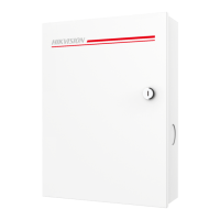
Hybrid Security Control Panel with Plastic Case
larm input
(DS-PHA20)
4 on-board zones , and 16 wired/wireless zones expadable(DS-PHA20),
o
r
8 on-board zones, and 56 wired/wireless zones expadable(DS-PHA64)
on-board outputs, and 18 wired/wireless outputs expadable (DS-PHA20),
r
on-board outputs, and 60 wired/wireless outputs expadable (DS-PHA64)
unction
upports up to 8 mobile phone numbers
1, PSTN expander interface
1, extended up to 20 inputs/outputs (with RS-485 module),
a
nd 9 wired keypads extendable (DS-PHA20),
r
, extended up to 64 inputs/outputs (with RS-485 module),
and 9 wired keypads extendable (DS-PHA64)
, 12V
ithium battery (-P model)
pplication &
rotocol
VMS-4200 (client software)
ik-Connect (mobile client)
SAPI: Supports client software and web client
loud P2P: Supports cloud P2P privacy protocol
DC09: ARC accessible (CID/SIA)
etwork
upports report push- notification to ARC & Cloud
dministrator: 1
anufactuer:1
Operator: 13 (DS-PHA20), 45 (DS-PHA64)
thers
–10 °C to 55 °C (-4 °F to +122 °F)
10% to 90% (No condensing)
lastic Case: 220 mm (8.6") × 152 mm (6.0") × 31.5 mm(1.2")
i-Fi
nterface &
omponent
1, front cover tamper-proof
1, RJ45 10M/100M Ethernet Interface
2a
2
b
2
c 2
2.2KΩ
NC
C
Z
C
Peripheral Security Detector
2.2KΩ
NO
C
Z
C
Security Control Panel
Security Control Panel
Security Control Panel
Peripheral Security Detector
Z
C
d.
Tamper-proof
Note: The 868 Mhz wireless siren can be enrolled to the hybrid control panel via the wireless receiver that is at the address of 9.
CAUTION
COPER OR COPER WIRE CANNOT BE
EXPOSED AT THE ELECTRICAL TERMINAL
CAUTION
A TWO-POLE DISCONNECTED
DEVICE (BREAKER) SHALL BE
PROVIDED WHEN INSTALLED
CAUTION
CABLES CAN ONLY BE ROUTED
THROUGH THE REAR PANEL. DO NOT
ROUTE THE ANTENNA WIRE THROUGH
THE ELECTRICAL BOARD
CON101
L
N
220V~
NULL
Line
Causc
Line
GND
4
AP
STA
AP
STA
UD15863B-B
©2020 Hangzhou Hikvision Digital Technology Co., Ltd. All rights reserved.
About this Manual
The Manual includes instrucons for using and managing the Product. Pictures, charts, images and all other informaon
hereinaer are for descripon and explanaon only. The informaon contained in the Manual is subject to change,
without noce, due to firmware updates or other reasons. Please find the latest version of this Manual at the Hikvision
website (hps://www.hikvision.com/).
Please use this Manual with the guidance and assistance of professionals trained in supporng the Product.
Trademarks
and other Hikvision's trademarks and logos are the properes of Hikvision in various jurisdicons. Other
trademarks and logos menoned are the properes of their respecve owners.
Disclaimer
TO THE MAXIMUM EXTENT PERMITTED BY APPLICABLE LAW, THIS MANUAL AND THE PRODUCT DESCRIBED, WITH ITS
HARDWARE, SOFTWARE AND FIRMWARE, ARE PROVIDED “AS IS” AND “WITH ALL FAULTS AND ERRORS”. HIKVISION MAKES
NO WARRANTIES, EXPRESS OR IMPLIED, INCLUDING WITHOUT LIMITATION, MERCHANTABILITY, SATISFACTORY QUALITY, OR
FITNESS FOR A PARTICULAR PURPOSE. THE USE OF THE PRODUCT BY YOU IS AT YOUR OWN RISK. IN NO EVENT WILL
HIKVISION BE LIABLE TO YOU FOR ANY SPECIAL, CONSEQUENTIAL, INCIDENTAL, OR INDIRECT DAMAGES, INCLUDING,
AMONG OTHERS, DAMAGES FOR LOSS OF BUSINESS PROFITS, BUSINESS INTERRUPTION, OR LOSS OF DATA, CORRUPTION
OF SYSTEMS, OR LOSS OF DOCUMENTATION, WHETHER BASED ON BREACH OF CONTRACT, TORT (INCLUDING
NEGLIGENCE), PRODUCT LIABILITY, OR OTHERWISE, IN CONNECTION WITH THE USE OF THE PRODUCT, EVEN IF HIKVISION
HAS BEEN ADVISED OF THE POSSIBILITY OF SUCH DAMAGES OR LOSS.
YOU ACKNOWLEDGE THAT THE NATURE OF INTERNET PROVIDES FOR INHERENT SECURITY RISKS, AND HIKVISION SHALL
NOT TAKE ANY RESPONSIBILITIES FOR ABNORMAL OPERATION, PRIVACY LEAKAGE OR OTHER DAMAGES RESULTING FROM
CYBER-ATTACK, HACKER ATTACK, VIRUS INSPECTION, OR OTHER INTERNET SECURITY RISKS; HOWEVER, HIKVISION WILL
PROVIDE TIMELY TECHNICAL SUPPORT IF REQUIRED.
YOU AGREE TO USE THIS PRODUCT IN COMPLIANCE WITH ALL APPLICABLE LAWS, AND YOU ARE SOLELY RESPONSIBLE FOR
ENSURING THAT YOUR USE CONFORMS TO THE APPLICABLE LAW. ESPECIALLY, YOU ARE RESPONSIBLE, FOR USING THIS
PRODUCT IN A MANNER THAT DOES NOT INFRINGE ON THE RIGHTS OF THIRD PARTIES, INCLUDING WITHOUT LIMITATION,
RIGHTS OF PUBLICITY, INTELLECTUAL PROPERTY RIGHTS, OR DATA PROTECTION AND OTHER PRIVACY RIGHTS. YOU SHALL
NOT USE THIS PRODUCT FOR ANY PROHIBITED END-USES, INCLUDING THE DEVELOPMENT OR PRODUCTION OF WEAPONS
OF MASS DESTRUCTION, THE DEVELOPMENT OR PRODUCTION OF CHEMICAL OR BIOLOGICAL WEAPONS, ANY ACTIVITIES
IN THE CONTEXT RELATED TO ANY NUCLEAR EXPLOSIVE OR UNSAFE NUCLEAR FUEL-CYCLE, OR IN SUPPORT OF HUMAN
RIGHTS ABUSES.
IN THE EVENT OF ANY CONFLICTS BETWEEN THIS MANUAL AND THE APPLICABLE LAW, THE LATER PREVAILS.
This product and - if applicable - the supplied accessories too are marked with "CE" and
comply therefore with the applicable harmonized European standards listed under the RE
Direcve 2014/53/EU, the EMC Direcve 2014/30/EU, the LVD Direcve 2014/35/EU, the
RoHS Direcve 2011/65/EU
2012/19/EU (WEEE direcve): Products marked with this symbol cannot be disposed of as
unsorted municipal waste in the European Union. For proper recycling, return this product to
your local supplier upon the purchase of equivalent new equipment, or dispose of it at
designated collecon points. For more informaon see: www.recyclethis.info
2006/66/EC (baery direcve): This product contains a baery that cannot be disposed of
as unsorted municipal waste in the European Union. See the product documentaon for
specific baery informaon. The baery is marked with this symbol, which may include
leering to indicate cadmium (Cd), lead (Pb), or mercury (Hg). For proper recycling, return
the baery to your supplier or to a designated collecon point. For more informaon
see:www.recyclethis.info
FCC Informaon
Please take aenon that changes or modificaon not expressly approved by the party responsible for
compliance could void the user’s authority to operate the equipment.
FCC compliance: This equipment has been tested and found to comply with the limits for a Class B
digital device, pursuant to part 15 of the FCC Rules. These limits are designed to provide reasonable
protecon against harmful interference in a residenal installaon. This equipment generates, uses
and can radiate radio frequency energy and, if not installed and used in accordance with the
instrucons, may cause harmful interference to radio communicaons. However, there is no
guarantee that interference will not occur in a parcular installaon. If this equipment does cause
harmful interference to radio or television recepon, which can be determined by turning the
equipment off and on, the user is encouraged to try to correct the interference by one or more of the
following measures:
—Reorient or relocate the receiving antenna.
—Increase the separaon between the equipment and receiver.
—Connect the equipment into an outlet on a circuit different from that to which the receiver is
connected.
—Consult the dealer or an experienced radio/TV technician for help.
This equipment should be installed and operated with a minimum distance 20cm between the
radiator and your body.
FCC Condions
This device complies with part 15 of the FCC Rules. Operaon is subject to the following two
condions:
1. This device may not cause harmful interference.
2. This device must accept any interference received, including interference that may cause undesired
operaon
2.2K Ω
2.2K Ω
Z
C
NC
NO
TAMPER
Detector
d
2e
e.
Dual-Zone Series Connecon
f.
Dual-Zone Parallel Connecon
2.2kΩ
Z
C
NC
C
8.2kΩ
NC
C
Security
Control Panel
Local Zone
Local Expanding Zone
2
f
2.2kΩ
Z
C
Local Zone
Security
Control Panel
8.2kΩ
Local Expanding
Zone
NO C
NO C