8. Main Remote Setting
A16381TMF2
23
Table B. Input and Output Number Display and Connectors
Input Number Display
Port
Factory Setting
Setting
Input/Output Indication Setting Item Indication
Input 1 CN3 1-2 Remote ON/OFF 1 (Level) 03
Input 2 CN3 2-3 Forbidding Remote Control after Manual Stoppage 06
Output 1 CN7 1-2 Operation 01
Output 2 CN7 1-3 Alarm 02
Output 3 CN8 1-2 Thermo-ON for Heating 06
Table C. Input and Output Settings and Display Codes
Code Indicated Input Output
00 Not set Not set
01 Room Thermostat (for Cooling) Operation
02 Room Thermostat (for Heating) Alarm
03 Remote ON/OFF 1 (Level) Cooling
04 Remote ON/OFF 2 (Operation) Thermo-ON for Cooling
05 Remote ON/OFF 2 (Stoppage) Heating
06 Forbidding Remote Control after Manual Stoppage Thermo-ON for Heating
07 Remote Cooling / Heating Change Total Heat Exchanger
08 Elevate Grille Input Elevate Grille Output
09 Setback Operation Fan Operation
10~15 Not set Not set
NOTES:
•
Change the optional setting aer waiting at least three minutes elapsed time aer start-up.
•
Do not set the elevating grille for the total heat exchanger.
•
Record the setting conditions for each input and output in the "Setting" column of the table.
8. Main Remote Setting
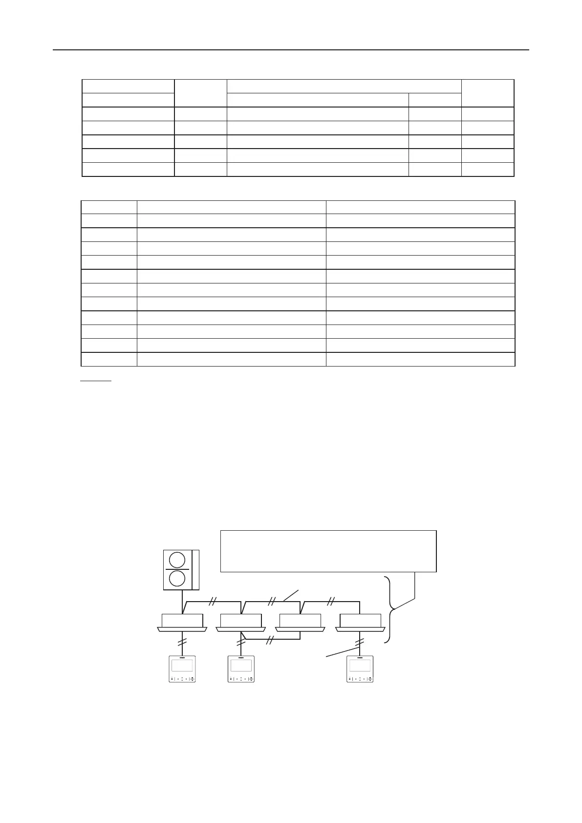
To change the sub remote controller to the main remote controller.
If multiple remote control groups exist in the same outdoor system, main/sub setting is automatically allocated.
Set the desired Wired Remote Controller as the "Main" remote controller.
•
Example of a refrigeration system containing a group of multiple controllers
The indoor and outdoor units need to correspond with the
functions shown in Table D. Some outdoor units cannot
use the settings "Power Up Setting" and "Autoboost".
H-LINK Transmission Cable
Transmission
Cable
SubSubMain
Main Controller — Only One Controller in Same Refrigerant System
Sub Controller — Controller in addition to the Main Controller in the same Refrigerant System
 Loading...