− 2 −
1-1-2. Removal of Housing (B) of the Housing (A), (B) Set [18] <17> (17)
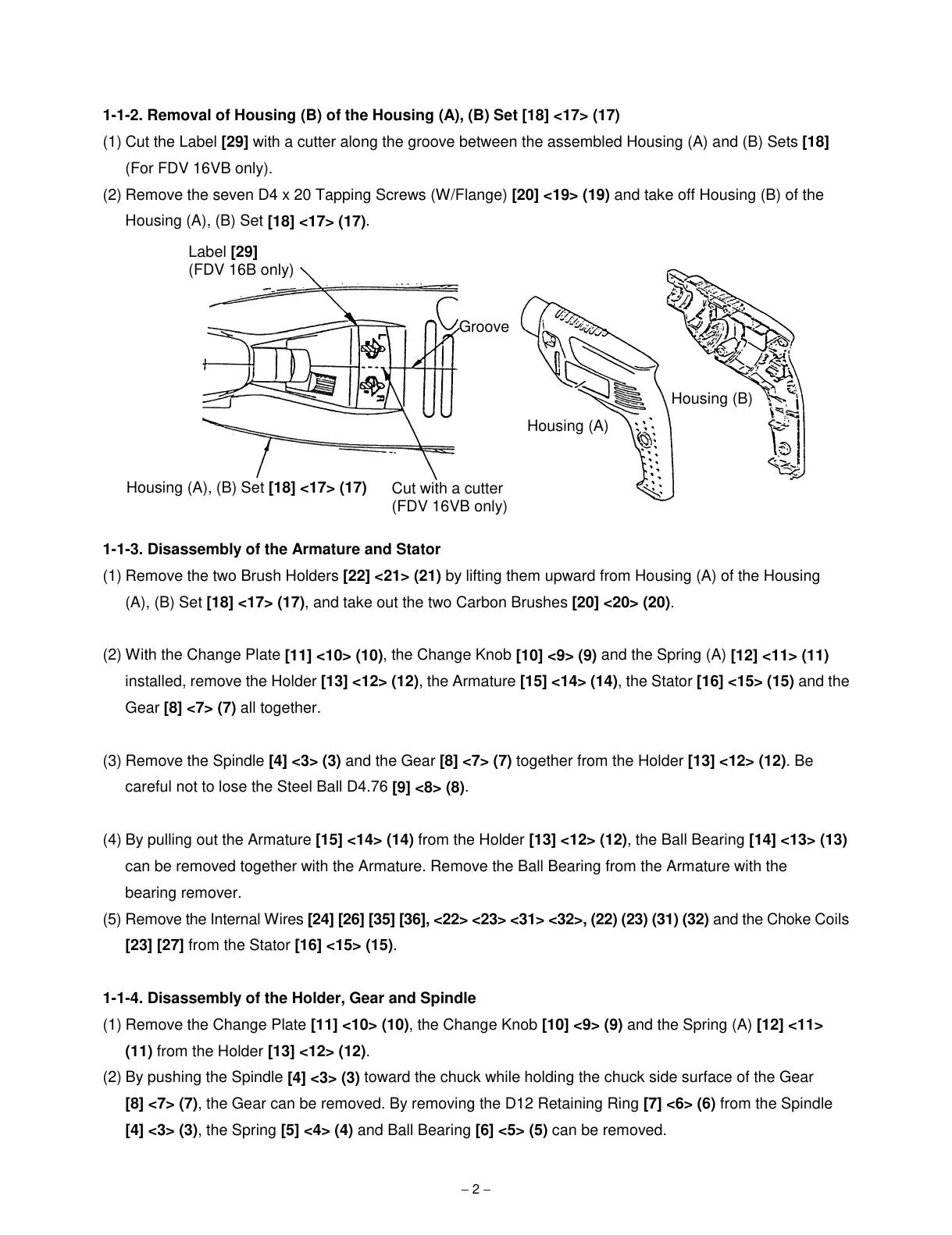
(1) Cut the Label
[29]
with a cutter along the groove between the assembled Housing (A) and (B) Sets
[18]
(For FDV 16VB only).
(2) Remove the seven D4 x 20 Tapping Screws (W/Flange)
[20] <19> (19)
and take off Housing (B) of the
Housing (A), (B) Set
[18] <17> (17)
.
1-1-3. Disassembly of the Armature and Stator
(1) Remove the two Brush Holders
[22] <21> (21)
by lifting them upward from Housing (A) of the Housing
(A), (B) Set
[18] <17> (17)
, and take out the two Carbon Brushes
[20] <20> (20)
.
(2) With the Change Plate
[11] <10> (10)
, the Change Knob
[10] <9> (9)
and the Spring (A)
[12] <11> (11)
installed, remove the Holder
[13] <12> (12)
, the Armature
[15] <14> (14)
, the Stator
[16] <15> (15)
and the
Gear
[8] <7> (7)
all together.
(3) Remove the Spindle
[4] <3> (3)
and the Gear
[8] <7> (7)
together from the Holder
[13] <12> (12)
. Be
careful not to lose the Steel Ball D4.76
[9] <8> (8)
.
(4) By pulling out the Armature
[15] <14> (14)
from the Holder
[13] <12> (12)
, the Ball Bearing
[14] <13> (13)
can be removed together with the Armature. Remove the Ball Bearing from the Armature with the
bearing remover.
(5) Remove the Internal Wires
[24] [26] [35] [36], <22> <23> <31> <32>, (22) (23) (31) (32)
and the Choke Coils
[23] [27]
from the Stator
[16] <15> (15)
.
1-1-4. Disassembly of the Holder, Gear and Spindle
(1) Remove the Change Plate
[11] <10> (10)
, the Change Knob
[10] <9> (9)
and the Spring (A)
[12] <11>
(11)
from the Holder
[13] <12> (12)
.
(2) By pushing the Spindle
[4] <3> (3)
toward the chuck while holding the chuck side surface of the Gear
[8] <7> (7)
, the Gear can be removed. By removing the D12 Retaining Ring
[7] <6> (6)
from the Spindle
[4] <3> (3)
, the Spring
[5] <4> (4)
and Ball Bearing
[6] <5> (5)
can be removed.
Label
[29]
(FDV 16B only)
Groove
Housing (B)
Housing (A)
Housing (A), (B) Set
[18] <17> (17)
Cut with a cutter
(FDV 16VB only)
 Loading...