Continued on Other Side
➜
4232CBM
Connected Building Module
INSTALLATION AND SETUP GUIDE
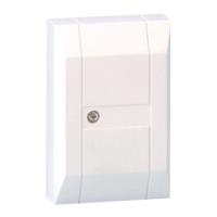
About the 4232CBM
The 4232CBM Connected Building Module is intended
to provide connection between compatible Honeywell
control panels and supported third-party software and
hardware products. It provides an interface between
the control panel’s ECP bus and external equipment
with either RS422 or RS232 interfaces. The connection
and configuration of this device is application-specific.
Please refer to the documentation for your external
equipment for information on which connection method
to use, and how to configure the external device to
communicate properly with the 4232CBM.
NOTE: The connected building features offered by the
4232CBM are not evaluated by ETL or UL.
Compatible Controls
Control Firmware Level
VISTA-15P, VISTA-15PSIA
VISTA-20P, VISTA-20PSIA
V9.1 or higher
VISTA-21iP, VISTA-21iPSIA V3.13 or higher
VISTA-128BPT,
VISTA-128BPTSIA
All versions
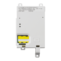
The 4232CBM module connects to the control panel
via the panel’s ECP terminals, and connects to the
external computer or other equipment via either RS422
or RS232 connections, according to the application.
The module is powered via the control panel’s ECP
+12VDC connection.
Wiring the Module
Refer to the diagram below for connections.
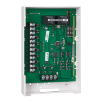
Mounting the Module
Mount the module inside the control panel cabinet
using double-sided tape (supplied). Make sure the
solder connections on the bottom of the PC board do
not touch the cabinet.
LED Indications
Four green LEDs indicate the following conditions:
LED Condition Meaning
On message waiting for the
external device
external
device
Flashing check connection to the
external device
Panel On or Blink keypad data waiting for the
external device
Slow Blink power on, normal operation
Flashing power on, not configured
Power
Off power off
Data Blink receiving data from the external
device
Specifications
Board Dimensions 3.75” W x 2.5” L x 0.875” D
Current Drain 50mA nominal; 75mA max
ECP Input Voltage 8-14VDC
Wire Run Length
RS232 Connection: 50 ft max with
24 AWG twisted pair wire
RS422 Connection: 1000 ft max
with 24 AWG twisted pair wire
ECP Connection: 900 ft max home
run with 22 AWG unshielded wire
Temperature 32°F (0°C) to 140°F (60°C)
1. 4232CBM to External Equipment Connection: For RS232 applications, connect the three RS232 lines
(GND, Tx and Rx) to the external equipment. For RS422 applications, connect the four RS422 lines (Tx+/-
and Rx +/-) to the appropriate points on the external equipment.
4232CBM-001-V0
CONTROL 4232CBM
CONTROL PANEL
ECP CONNECTION
RS422
CONNECTIONS
9-PIN
CONN.
RS232
CONNECTIONS
4232CBM PC BOARD
DATA (RECEIVING)
(MESSAGE WAITING)
PANEL (KEYPAD DATA)
POWER
LED INDICATORS
STANDARD
9-PIN
SERIAL
CONNECTOR
NOT USED
DATA OUT
GND
DATA I N
12VDC
4-WIRE
HARNESS
TX
TX
RX
RX
RX (YELLOW)
GND (BLACK)
TX (GREEN)
12VDC (RED)
Ω
120
NOTE: IF WIRE RUN TO RS422 DEVICE EXCEEDS 100 FT, INSTALL
120 OHM RESISTOR BETWEEN RX AND RX TERMINALS ON
THE 4232CBM.
RESISTOR
5(GND)
3(TX)
2(RX)
GND
RX
TX
NOTES:
A. The connections shown above are used for most applications where the external equipment has a male DE-9
connector (for example, PCs and most home automation equipment).
B. For RS422 applications, refer to the documentation for your external equipment.