5834
58345834
5834-
--
-4
44
4
Series
SeriesSeries
Series
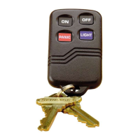
Wireless Key Transmitter
Wireless Key TransmitterWireless Key Transmitter
Wireless Key Transmitter
INSTALLATION AND SETUP GUIDE
GENERAL INFORMATION
The 5834-4/5834-4EN key transmitters are portable wireless transmitters for use only with wireless alarm systems that support 5800 Series receivers (ex. VISTA series,
L
YNX PLUS, LYNX Touch). The 5834-4EN is identical to the 5834-4 except the 5834-4EN has a plated bezel and key ring. References to the 5834-4 throughout this
document refer to both models.
• Buttons are typically used for arming and disarming, but can be programmed for any
appropriate zone response.
• A button must be pressed and held until the LED begins to flash to activate a button
function. This press and hold feature minimizes the possibility of accidental
transmissions. (Refer to the Loop Number diagram at right).
• The factory-installed replaceable lithium battery provides power for up to five (5) years.
PROGRAMMING
• The 5834-4 transmitter provides up to eight (8) functions and has an
Optional high security (encrypted) mode that sends rolling-code
encrypted messaging to the RF receiver.
High Security Mode Note: This product is set to high security
(encrypted) mode by the factory, and must be used with a receiver or
control that supports high security mode. i.e., 5881EN, 5883, 6150RF,
or 6160RF receiver or LYNXR Series control panel (Rev 13.1 or higher).
For complete details on how to program the transmitter at the control panel, see the control unit's Installation Instructions
. When programming, note the following:
• Each 5834-4 transmitter has two unique serial numbers assigned during manufacture.
• Each button on the unit also has a distinct "loop" number (refer to the Loop Number diagram
at right) that you must program into the control panel during installation.
• Assign each button to an individual zone and designate the Input Type as "BR" (Button Type).
• When prompted for the serial number, press and release the appropriate button(s) twice, or,
manually enter the serial number at the keypad.
NOTE: Serial #2 is one (1) digit higher than serial #1, and is printed on the rear of the transmitter.
CHANGING HIGH SECURITY / STANDARD MODE IN COMPATIBLE RECEIVERS
AND LOCALLY IN AN RF KEYPAD (eg., 6150RF)
If used with LYNXR Series controls earlier than Rev
Standard Mode must be selected.
The key fob is defaulted to high security mode. To change the mode do the following:
1. Select desired mode:
(LED flashes Red when transmit
(LED flashes Green when transmitting)
Press any button to check the LED color.
2. When High Security mode is selected:
• High Security mode MUST be activated in the control panel, see table below.
• If the key fob is enrolled into the panel, put the security system into Go/No Go Mode
then press the appropriate buttons as follows:
Simultaneously hold down until beeps sound…
buttons (system beeps twice to confirm)
buttons (system beeps twice
Note: Repeat for second serial number, if used.
• If the key fob is enrolled locally into a 6150RF, go to Step 3 of 6150RF “Programming
WITH Local Wireless Keys”.
Loop Numbers for the 5834
5834-008-V2
SERIAL #1
LOOP 4
SERIAL #1
LOOP 1
SERIAL #2
LOOP 1
SERIAL #2
LOOP 3
BUTT
ON 4BUTTON 3
BUTTON 2BUTTON 1
SERIAL #1
LOOP 3
SERIAL #2
LOOP 4
SERIAL #1
LOOP 2
SERIAL #1 FUNCTIONS ACTIVATE WHEN THE RESPECTIVE
BUTTON IS HELD DOWN UNTIL THE LED FLASHES.
SERIAL #2 FUNCTIONS ACTIVATE WHEN THE TWO RESPECTIVE
SERIAL #2 BUTTONS ARE PRESSED AT THE SAME TIME AND
HELD DOWN UNTIL THE LED FLASHES.
NOTE
1.
2.
SERIAL #2
LOOP 2
A
C
B
D
Using a Button: To activate a programmed function, press and hold
the appropriate key(s) until the LED begins to flash (about ½ second).
SIA INSTALLATIONS: Use only serial #2/loop 2 (C & D keys) for the
panic function. Do not use serial #1/loop 1 (D) key.
• On most control panels, if the wireless key is assigned to arm and disarm the system, you must assign it to a user in order for it to operate. This is accomplished
through User Code programming at the control panel. See control panel’s Installation and Setup Guide for specific instructions; table below summarizes the procedures.
• If programming arming and disarming functions on both serial numbers, each serial number must be assigned to a separate user.
On Vista 32/40/50/50P/100 and up
You must assign a user to the button in order for it to operate.
To assign a user number to the Arm/Disarm button:
1. Enter [4-digit User Code] + [8] + [User No.] + [new User Code].
2. Answer Yes or No to the “Open/Close Report ?” question.
3. Answer Yes to the “RF Button ?” question.
4. Enter the zone number assigned to the button.
5. Keypad display shows summary of user information.
6. Test all functions for proper operation.
You must assign a user to the button in order for it to operate, and must enter a
sequence of keystrokes as described below.
NOTE: There is a two-second timeout for keystroke commands on Vista P series
panels, therefore you must enter the keystrokes as quickly as possible.
1. Enter [4-digit Master Code] + [8] + [User Number] +
[# 4] + [two digit zone number] assigned to the fob.
2. Test all functions for proper operation.
EXHIBIT 7-1A
INSTALLATION INSTRUCTIONS