SOLID STATE ECONOMIZER SYSTEM
63-2484—03 14
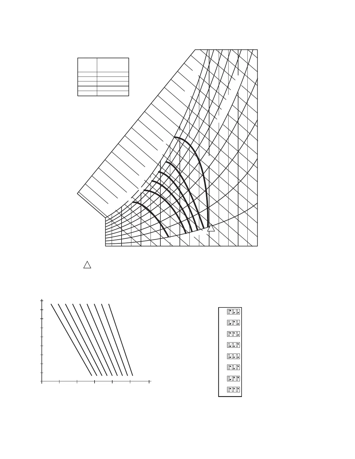
Fig. 19. Partial psychrometric chart with single C7400C enthalpy sensor and the W7212 logic module A, B, C, D, and E
performance curves.
Fig. 20. C7400A Sensor output current vs. relative humidity.
Fig. 21. C7660 Temperature Sensor Dip Switch Settings.
CONTROL
CURVE
A
B
C
D
E
CONTROL POINT
APPROX. °F (°C)
AT 50% RH
73 (23)
70 (21)
67 (19)
63 (17)
55 (13)
12 14 16 18 20 22 24 26 28 30 32 34 36 38 40 42 44 46
90
100
80
70
60
50
40
30
20
10
ENTHALPY—BTU PER POUND DRY AIR
85
(29)
90
(32)
95
(35)
100
(38)
105
(41)
110
(43)
35
(2)
35
(2)
40
(4)
40
(4)
105
(41)
110
(43)
45
(7)
45
(7)
50
(10)
50
(10)
55
(13)
55
(13)
60
(16)
60
(16)
65
(18)
65
(18)
70
(21)
70
(21)
75
(24)
75
(24)
80
(27)
80
(27)
85
(29)
90
(32)
95
(35)
100
(38)
APPROXIMATE DRY BULB TEMPERATURE— °F (°C)
A
A
B
B
C
C
D
D
M23879A
RELATIVE HUMIDITY (%)
1
1
HIGH LIMIT CURVE FOR W7210D, W7212, W7213, W7214, W7340C.
E
E
20
10
30
40
50
60
70
80
90
100
605040 70 80 90 100
PERCENT RH
TEMPERATURE F (C)
M9101
C7400A OUTPUT CURRENT
4 mA
6 mA
8 mA
10 mA
20 mA
18 mA
16 mA
14 mA
12 mA
(4) (10) (16) (21) (27) (32) (38)
ON
OFF
132
78ºF
ON
OFF
132
73ºF
ON
OFF
132
68ºF
ON
OFF
132
63ºF
ON
OFF
132
58ºF
ON
OFF
132
55ºF
ON
OFF
132
53ºF
ON
OFF
132
48ºF
M27636
DIP SWITCH
POSITION
CHANGEOVER
TEMPERATURE
 Loading...


