SOLID STATE ECONOMIZER SYSTEM
19 63-2484—03
a
For single enthalpy control, the module compares outdoor enthalpy to the ABCD setpoint.
b
Power at N terminal determines Occupied/Unoccupied setting:
• W7212: 24 Vac (Occupied), no power (Unoccupied). W7212C returns to minimum position on CO
2
sensor failure.
• W7213,W7214: No power (Occupied), 24 Vac (Unoccupied).
c
Modulation is based on the mixed air sensor signal.
d
Modulation is based on the DCV signal.
e
Modulation is based on the greater of DCV and mixed air sensor signals, between minimum position and either maximum
position (DCV) or fully open (mixed air signal).
f
Modulation is based on the greater of DCV and mixed air sensor signals, between closed and either maximum position (DCV)
or fully open (mixed air signal).
NOTES:
— DCV and Free Cooling have setpoints and LED indications.
— For models with a B terminal (W7213):
No power to B: cooling mode, free cool enabled. Module follows logic detailed above.
24V power to B: heating mode, free cool disabled. Actuator drives to minimum position (closed when Unoccupied).
— For models with an O terminal (W7214):
24V power to O: cooling mode, free cool enabled. Module follows logic detailed above.
No power to O: heating mode, free cool disabled. Actuator drives to minimum position (closed when Unoccupied).
SETTINGS AND
ADJUSTMENTS: W7212
Equipment Damage Hazard.
Excessive force can damage potentiometer
controls.
Use a small screwdriver when adjusting enthalpy
changeover and minimum damper position controls.
Potentiometers with small screwdriver adjustment slots,
located on device face, provide adjustments for several
parameters (see Fig. 27 for locations on device):
— DCV setpoint.
— Minimum damper position.
— DCV maximum damper position.
— Enthalpy changeover.
— Exhaust setpoint.
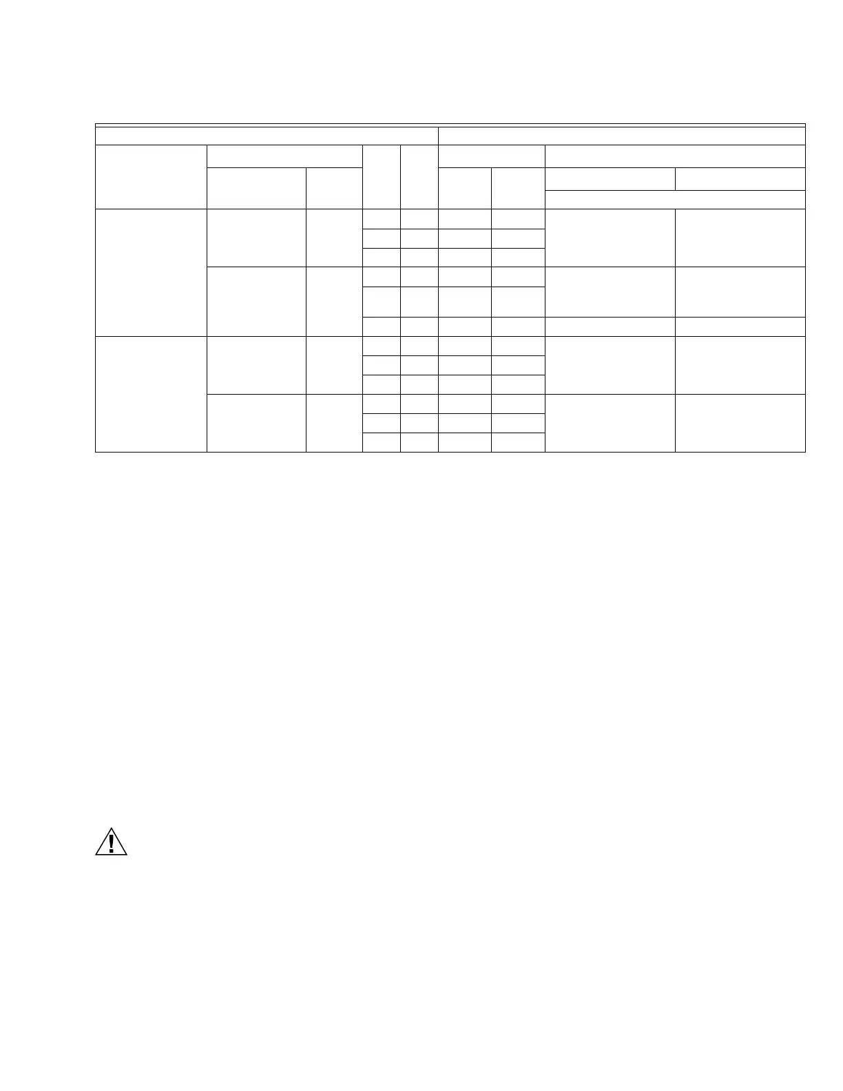
Table 5. W7212 Economizer I/O Logic.
INPUTS OUTPUTS
Demand Control
Ventilation (DCV)
Enthalpy
a
Y1 Y2
Compressor N Terminal
b
Outdoor Return Stage 1 Stage 2
Occupied
b
Unoccupied
b
Damper
Below set (DCV
LED Off)
High (Free
Cooling LED Off)
Low On On On On Minimum position Closed
On Off On Off
Off Off Off Off
Low (Free
Cooling LED On)
High On On On Off
Modulating
c
(between
min. position and full-
open)
Modulating
c
(between
closed and full-open)
On Off Off Off
Off Off Off Off Minimum position Closed
Above set (DCV
LED On)
High (Free
Cooling LED Off)
Low OnOnOn On
Modulating
d
(between
min. position and DCV
maximum)
Modulating
d
(between
closed and DCV
maximum)
On Off On Off
Off Off Off Off
Low (Free
Cooling LED On)
High On On On Off
Modulating
e
Modulating
f
On Off Off Off
Off Off Off Off
 Loading...


