EasyManuals Logo
Home>Honeywell>Controller>DBC2000 Series

Honeywell DBC2000 Series User Manual

Honeywell DBC2000 Series
24 pages
To Next Page IconTo Next Page
To Previous Page IconTo Previous Page
Page #3 background imageLoading...
Page #3 background image
ENI7003R8 KO65 2013
3
Table 4: Flame detection systems
Detector
type
Flame detector model no.
Standard stable flame
current on jack plug
UV detector C7027A, C7035A, C7044A < 100m A (min)
14µA (max)
Flame rod Flame rod or rectifying optical sensors,
C7012A,G (UV) or IRD1020.1 (IR)
< 15m 14µA (min)*
4µA (max)*
* When using a flame rod, the current on the flame jack plug is inverted. See also Fig 4-2.
Flame detector leads are colour coded. The blue lead wire must be connected to the F terminal (T23) and the
white lead wire to the G terminal (T24). The UV sensing tube is polarity sensitive. Reversing the lead wires
even momentarily will destroy the UV sensing tube.
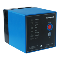
Other manuals for Honeywell DBC2000 Series

Questions and Answers:

Question and Answer IconNeed help?

Do you have a question about the Honeywell DBC2000 Series and is the answer not in the manual?

Honeywell DBC2000 Series Specifications

General IconGeneral
BrandHoneywell
ModelDBC2000 Series
CategoryController
LanguageEnglish

Related product manuals