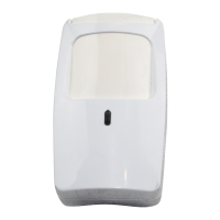
DT-7235/DT-7235T DUAL TEC
®
Motion Sensor Installation Instructions
TT
Step 1
Separate the sensor housings and remove
Printed Circuit Board (PCB).
Use a small screwdriver to unfasten the hous-
ing latch and separate the sensor housings.
Push outward on the PCB latch to lift the PCB
out of the housing.
Step 3
Wire the sensor.
Observing the proper polarity, wire the unit as
shown in the illustration below, use 1.02 to 0.64 mm
(18 to 22 AWG) wire.
Step 2
Mount the sensor.
Break out the mounting/wiring knockouts and
mount the sensor in an appropriate location.
An ideal location meets the following objectives:
• Allows a clear line-of-sight to all areas to
protect.
• Does not directly face windows.
• Avoids close proximity to moving machinery,
fluorescent lights, and heating/cooling
sources.
• See Special Instructions for installations
containing pets.
NOTE: maximum range is obtained at a
mounting height of 2.3 m (7’6”).
Knockout
Housing
latch
PCB latch
FRONT HOUSING
REAR HOUSING AND PCB
Terminal Block (TB1)
PCB
LED
(DS1)
LED Enable
(Cut or remove
LED enable jumper
J1* to disable LED)
Alarm
500 mA
30 VDC
Power
25 mA
7.5-16 VDC
(UL: 8.9-14.5 VDC)
Step 4
Walk-test the sensor.
After returning the PCB to the rear hous-
ing, reassemble the sensor housing. Ap-
ply power to the sensor and begin walk-
test when the red LED is off.
Walk across the detection area at the
ranges to be covered. The red LED should
indicate an alarm condition after 2 to 4 nor-
mal steps. When there is no motion in the
detection area the LED should be off.
DT-7235
TB1
TB2
DT-7235T
Alarm
500 mA
30 VDC
Power
25 mA
7.5-16 VDC
(UL: 8.9-14.5 VDC)
TB1
DT-7235T
Tamper
50 mA
24 VDC
TB2
Remove look-down
mask for non-pet
applications.
* J1 may be located in either location
indicated in the above illustration.