Bedienungsanleitung
Melderentnahmewerkzeug und Zubehör
Operation Instruction
Detector removal tool and accessories
(Art.-Nr. / Part No. 805580)
798929
Technische Änderungen vorbehalten!
Technical changes reserved!
10.2009
D
GB
© 2009 Honeywell International Inc.
Novar GmbH a Honeywell Company
Dieselstraße 2, D-41469 Neuss
Internet: www.esser-systems.de
E-Mail: info@esser-systems.de
D
Achtung!
Diese Anleitung ist vor der Inbetriebnahme genau
durchzulesen. Bei Schäden die durch
Nichtbeachtung der Anleitung verursacht werden,
erlischt der Garantieanspruch. Für Folgeschäden, die
daraus resultieren, wird keine Haftung übernommen.
Allgemein
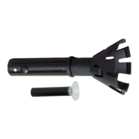
Das Melderentnahmewerkzeug wird zur Entnahme
der automatischen Brandmelder Serie 9x00 und
IQ8Quad aus dem Meldersockel eingesetzt. In
Verbindung mit den Teleskopstangen wird die
Entnahme des Melders bei größeren Deckenhöhen,
außerhalb des Handbereiches, ermöglicht.
Mit dem aufschraubbaren Saugnapf eignet sich das
Entnahmewerkzeug auch zum Abziehen/Aufsetzen
der Melderabdeckkappen Serie 9x00 (Art.-Nr.
789855/-56) und IQ8Quad (Art.-Nr. 805588/-89)
sowie der Sockelabdeckung für IQ8Quad Melder
(Art.-Nr. 805587).
Art.-Nr. Bezeichnung
805580 Entnahmewerkzeug
062427 Kunststoff-Teleskopstange bis 4,5 m
062426 Teleskopverlängerung
(Länge 1,13 m) für 062477
805581 Adapter für Teleskopstange 769813
769813 Teleskopstange (Länge 3,75 m)
769814 Teleskopverlängerung (Länge 4 m)
Ergänzende und aktuelle Informationen
Die Produktangaben entsprechen dem Stand
der Drucklegung und können durch
Produktänderungen, geänderte Normen /
Richtlinien ggf. von den hier genannten
Informationen abweichen.
Aktualisierte Informationen zur Projektierung,
Inbetriebnahme und Wartung von Brand-
meldern siehe unter www.esser-systems.de.
Montage
Sicherungsknopf am Melderentnahmewerkzeug
drücken und das Werkzeug mit gedrücktem Knopf auf
die Teleskopstange aufsetzen und bis zum Einrasten
drehen.
Verwendung des Adapters (Art.-Nr. 805581)
Das Entnahmewerkzeug kann mit dem Adapter auch in
Verbindung mit der Teleskopstange (Art.-Nr. 769813)
eingesetzt werden (Abb. 2).
Entnehmen oder Einsetzen von automatischen
Brandmeldern (Abb. 3)
Das Servicepersonal stellt sich möglichst nah und
direkt unter den Brandmelder. Das
Entnahmewerkzeug leicht angewinkelt auf den
Melderkopf und die seitlichen Öffnungen drücken, bis
es einrastet. Der Melder kann im Uhrzeigersinn aus
dem Sockel herausgedreht und entnommen werden.
Zum Wiedereinsetzen eines Melders muss dieser auf
das Entnahmewerkzeug aufgesteckt werden, bis er
dort einrastet. Melder exakt unter dem Meldersockel
ausrichten und durch eine Drehbewegung gegen den
Uhrzeigersinn in den Meldersockel eindrehen. Das
Entnahmewerkzeug abziehen.
Technische Daten
Gehäuse : Kunststoff, PVC
Farbe : schwarz
Gewicht : ca. 124 g
Maße (H) : 185 mm
Min. Durchmesser : 29 mm
Max. Durchmesser : 85 mm
GB
Warning!
This manual must be studied carefully before
commissioning. Claims under warranty will be
invalidated in the event of damage caused by non-
compliance with the instructions. No liability is accepted
for any resulting consequential loss.
General
The detector removal tool is used to remove the
automatic Fire alarm detectors series 9x00 and
IQ8Quad from the detector base. The optional
telescopic pole provides the removal of detectors,
mounted at higher ceilings out of the close-up range.
To remove or fit the detector dust cover series 9x00
(Part No. 789855/-56) und IQ8Quad (Part No. 805588/-
89) or base cover (Part No. 805587) from the detectors
the supplied sucker must be screwed onto the removal
tool.
Part No. Description
805580 Removal tool
062427 Plastic telescopic pole up to 4,5 m
062426 Extension telescopic pole
(length 1,13 m) for 060477
805581 Adapter for telescopic pole 769813
769813 Telescopic pole (length 3,75 m)
769814 Extension telescopic pole (length 4 m)
Additional and updated Informations
The product specification relate to the date of
issue and may differ due to modifications
and/or amended Standards and Regulations
from the given informations.
For updated informations to commissioning and
maintenance of Fire alarm detectors refer to
www.esser-systems.de.
Mounting
Attach removal tool to pole simply by pressing the
button on the removal tool and inserting it into the pole.
Turn it until the button clips into place.
Using the adapter (Part No. 805581)
The removal tool may be attached to the telescopic
pole (Part No. 769813) via the adapter (Fig. 2).
Remove or remount automatic fire detectors (Fig. 3)
The service personal position as near to directly under
the detector as possible to simplify the task. Simply
offer tool up-to sensor head n and grip on the side
vents of the detector. The tool should click into place.
Next simply turn the tool clockwise until the sensor
detaches from the base and remove detector.
To remount the detector place it into the removal tool.
The detector should clip into place. Next offer the
removal tool lightly angled onto the base. Once over
the base, move turn the tool in an anti-clockwise
direction until it engages back into place. The removal
tool can be detached.
Specifications
Housing : Plastic, PVC
Colour : black
Weight : approx. 124 g
Dimensions (h) : 185 mm
Smallest Diameter : 29 mm
Largest Diameter : 85 mm