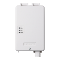
IPOTS-COM IP/POTS Digital Communicator
Product Installation Document
PN LS10184-000GE-E:B 6/6/2018 18-244
1 Description
The IP/POTS Communicator card transmits system status (alarms, troubles, AC loss, etc.) to a Central Station via the public switched
telephone network and/or Internet protocol. It also allows remote programming or interrogation of the control panel using AlarmNet®.
2 Installation
2.1 50 Point and 198 Point Panel Installation
1. Disconnect all power from the fire panel.
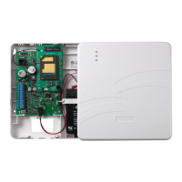
2. Remove the two screws at the bottom of the board that are used to attach the board to the chassis.
3. Replace the screws with two 3/4” standoffs from the hardware kit.
4. Insert the plastic PCB spacer into the hole marked “Communicator Support”.
5. Install the 5” cable from the hardware kit into the header on the main PCB marked “Communicator” and the header on the IPOTS-COM
labeled “Main Board Int” as shown below.
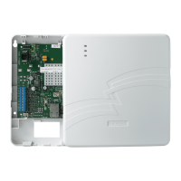
6. Holding the IPOTS-COM on an angle, align the pins on the plastic keypad bezel to the holes on the sides of the communicator.
7. Lay the IPOTS-COM flat and snap it onto the PCB spacer.
WARNING: THIS SYSTEM CONTAINS STATIC SENSITIVE COMPONENTS
WEAR A PROPER GROUNDING WRIST STRAP AND WORK ON A STATIC-SAFE WORKSPACE TO PROTECT
ELECTRONIC ASSEMBLIES.
RTN- OUT-
COMMUNICATOR
DISPLAY
RTN+OUT+
BATTERY
N/L2EARTHH/L1
USB-A
CNO NC
CNO NC
CNCNO
SUPV
TRBL
ALRM
ANN-LC
Remove screws and install standoffs
Insert PCB spacer
Plastic pins
Cable
header