1
NOTE: It is strongly recommended that any personnel
installing a Galaxy Dimension panel undertake appropriate
training. This training is supplied free of charge and can be
arranged by contacting Honeywell Security.
A full technical installation manual will be given to each
installer at the training session. Additional manuals can be
purchased from your distributor.
Additionally, the installation manual is available from the
Honeywell Security website:
www.honeywell.com/security
Variants
The Galaxy Dimension is available in 4 variants:
GD-48; GD-96; GD-264; GD-520. The differences
between each variant are shown in the following table.
Variant On-board
PSTN Dialler
RS485
Buses
Zones
Min/Max
STD
users*
GD-48 YES 1 16/48 94
GD-96 YES 2 16/96 242
GD-264 YES 2 16/264 987
GD-520 YES 4 16/520 987
*Excluding Manager, Authorisation, Engineer and ATM codes.
NOTE: The E485-2 Expansion module gives 2 extra Bus
lines (lines 3 and 4). The addition of the E485-2
to a GD-264 system turns it into a GD-520
system.
Setup
In order to get the system up and running, mount the panel
and connect and address all peripherals as described
below, before finally powering the system.
Peripheral Wiring
The following peripherals can be connected to the panel:
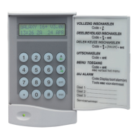
All bus lines: Mk7 LCD Keypad/Keyprox; TouchCenter;
MAX
3
; DCM; RIO; PSU.
Bus line 1 only: Telecom; RS232; ISDN; Ethernet; Audio
Interface
NOTE: The system must be wired in a daisy-chain
configuration. Spur and star configurations must
not be used. The recommended cable used to
connect the RS485 (AB) line is twisted pair
screened cable (Belden 8723 equivalent).
Panel
Keypad/
Keyprox
Touch
Center
RIO &
DCM
PSU
Audio
Interface
+12V +
+
+ X*
+12V
GND –
–
– 0V
GND
A A
G
A A
A
B B
Y
B B
B
*Do not connect +12V terminals between panels and
remote power supplies
Panel Telecom RS232 ISDN Ethernet
+12V +12V +12V 12V +
GND - – GND -
A A A A A
B B B B B
RS485 Peripheral Wiring
Peripheral Addressing
The address on most peripherals is set by either jumpers or
a rotary switch. These must be set before the system is
powered up. See the instructions with the peripheral for
details. The following table identifies the available
peripheral addresses:
VALID ADDRESSES
Peripheral Line GD-48 GD-96 GD-264 GD-520
Mk7 Keypad
1
2
3-4
0-2,B-F
-
-
0-2,B-F
0-2,B-F
-
0-2,B-F
0-6,F
-
0-2,B-F
0-6,F
0-6,F
MK7
Keyprox
1
2
3-4
0-2
-
-
0-2
0-3
-
0-2
0-3
-
0-2
0-6
0-6
TouchCenter
1
1
2
3-4
0-2
-
-
0-2
0-3
-
0-2
0-3
-
0-2
0-6
0-6
RIO/PSU 1
2
3-4
2-5
-
-
2
2
-5
0-5
-
2
2
-9, A-F
0-9, A-F
-
2
2
-9 & A-F
0-9 & A-F
0-9 & A-F
MAX/DCM
Reader
1
2
3-4
0-3
-
-
0-3
0-3
-
0-3
0-3
-
0-7
0-7
0-7
Telecom 1 (E) (E) (E) (E)
RS232 1 (D) (D) (D) (D)
ISDN 1 (C) (C) (C) (C)
Ethernet 1 (B) (B) (B) (B)
Peripheral Addresses
NOTES: 1. A single TouchCenter can be fitted to each bus line.
2. If RIO 2 on-board is set to line 0 (dip sw 8) then the first
external RIO can use address 1 to give an extra 8 zones where
needed.
Mains Supply Wiring
This product is not suitable for installation, maintenance or
connection by the user. A competent, qualified engineer,
with for example NSI approval, must carry out installation
and maintenance.
Warning: A means of isolation from the mains supply
must be provided within two metres of the
control panel. Where live and neutral
supplies can be identified, a fused spur with
a 3A fuse must be fitted on the live circuit.
Where live and neutral circuits cannot be
readily identified, 3A fuses must be fitted to
both circuits.
Connect the wires to the mains terminal block in the panel
as follows:
• Blue (neutral) – connect to terminal N
• Green/Yellow (earth) – connect to terminal E
• Brown (live) – connect to terminal L
Galaxy Dimension Quick-start Guide