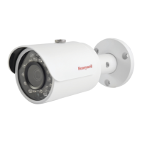
HBD3PR2 True Day/Night Indoor/Outdoor IR Bullet IP Camera
Before you begin, check that you have received all of the parts listed below. If any parts are missing
or damaged, contact your dealer immediately.
•
•
•
Camera
Documentation CD
Quick install guide
Allen key (L-wrench)
•
•
Self-tapping screws (×3)
Plastic wall anchors (×3)
Mounting template
b. Insert the microSD card into the microSD card slot as
shown in the picture at right.
c. Replace the control panel.
2. Connect the camera with the Ethernet cable and the power
cable.
•
•
A Phillips screwdriver
A drill with an appropriately-sized drill bit for pre-drilling holes for the screw anchors.
Installation and servicing should be performed only by qualified
and experienced technicians to conform to all local codes and to maintain your
warranty.
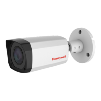
1.
Use the supplied Allen key to loosen the adjusting screws
on the bracket arm.
2. Set the camera to the desired position.
3. Tighten the adjustment screws.
Preparing the Mounting Surface
1. Inspect the site where you want to install the camera. The mounting surface must be
flat and capable of supporting at least three times the weight of the camera.
2. Remove the backing from the mounting template sticker and affix the sticker to the
mounting surface.
Note If you are using the side exit for the cable, note the orientation of the cable exit
notch. In outdoor installations the notch should point downwards to prevent water from
entering the camera housing.
Document 800-21233V1 – Rev A– 10/2015
© 2015 Honeywell International Inc. All rights reserved. No part of this publication may be reproduced by any means without written permission from Honeywell. The information in this publication is believed to be accurate in all respects. However,
Honeywell cannot assume responsibility for any consequences resulting from the use thereof. The information contained herein is subject to change without notice. Revisions or new editions to this publication may be issued to incorporate such changes.
3.
Drill three screw holes at the locations indicated on the mounting template sticker and
insert the three supplied plastic anchors in the holes.
4. If you want to store the cables inside the wall or ceiling, drill a hole at the cable exit position
on the mounting template and then pull the cables through the hole.
1. If local storage is needed, insert a micro SD card into the micro SD card slot
according to the following steps:
a. Use a Phillips screwdriver (not supplied) and remove the control panel cover
on the outside of the camera.
Adjusting the Zoom and Focus Settings
The cameras connected to a PoE port of the Honeywell Embedded NVR can be configured
with the NVR directly.
To log on to the camera with a PC, perform the following steps:
1. Install the Honeywell Config Tool from the software and the documentation CD, find the
camera and open the web browser with the Honeywell Config Tool
2. Log on to the camera as the admin user. The default user name is admin (case-sensitive)
and the default password is 1234.
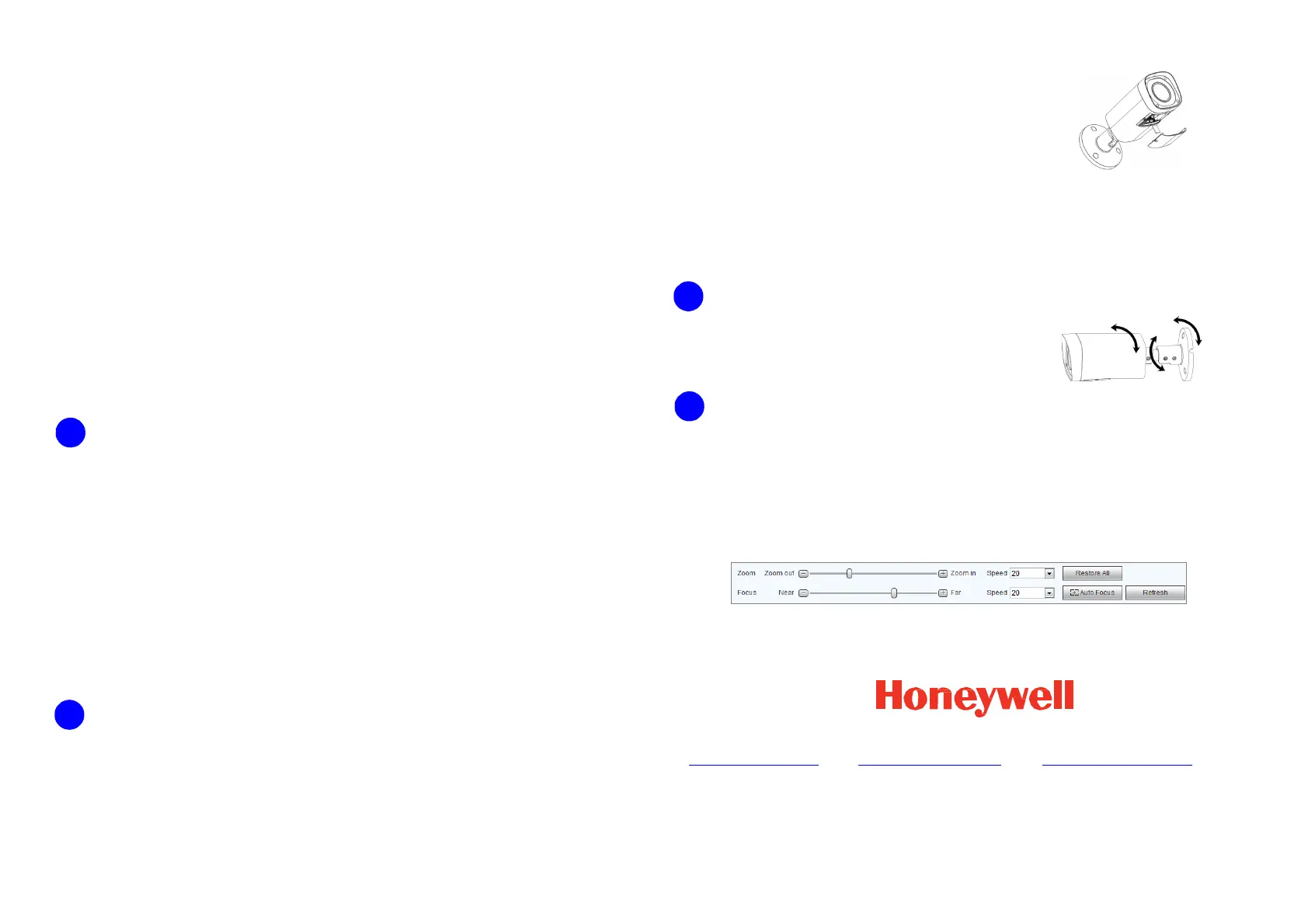
3. Go to Setup CameraConditionsZoom and Focus. The following panel appears:
• Click Zoom in + or Zoom out – to zoom in or out.
• Click Near – or Far + to focus near or far, or click Auto Focus to enable auto focus.
+1 800 323 4576
www.honeywell.com/security
+1 44 (0) 1928 754 028
www.honeywell.com/security/uk
(Europe only)
+86 21 22196888
www.asia.security.honeywell.com
(Asia Pacific only)
a. Connect one end of the Ethernet cable to the RJ-45 port on the camera.
b. If the other end of the Ethernet cable is NOT connected to a PoE (Power-over-
Ethernet) switch or NVR, connect the power connector of the camera to a 12 V
DC power source.
3. Attach the camera assembly to the mounting surface using the supplied screws.
 Loading...