INSTALLATION INSTRUCTIONS
HPZC10*
HONEYWELL HYDRONIC PRO
ZONE VALVE CONTROL PANEL
WHAT'S IN THE BOX?
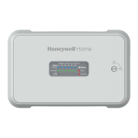
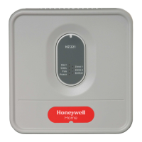
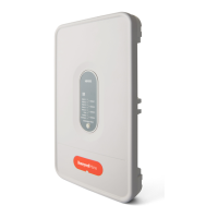
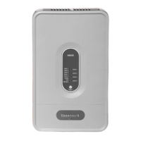
• Hydronic Zone Panel
• Mounting Hardware (3 Screws and 3 Wall Anchors)
•2, 2-Amp Fuses
• Install Manuals (English & French)
1. Disconnect power supply before beginning
installation to prevent electrical shock or
equipment damage.
2. Use copper conductors only.
3. Use only NEC Class 1 wire for all line voltage
wiring connections. Class 1 wires must be
rated for at least 167 °F (75 °C).
4. For installation by professionals only.
PANEL SPECIFICATIONS
Table 1.
1
Each transformer is protected with a 2 Amp replaceable fuse.
2
Transformers have a Class 2 output and are rated for 24V, 40VA at 25 °C. It is up to the installer to ensure that the 40VA
transformer rating is not exceeded.
3
All circulator relay connections are rated for 5A full load and 30A locked rotor (1/6 to 1/2HP depending on technology)
at 120VAC. Check circulator plate ratings to ensure full load current is not exceeded.
Model Zones
Transformers
1
Input Power
Electrical Rating for
Main Burner, End
Switch Burner, and
Zones
2
Electrical Rating for
Pump End Switch and
Priority Pump
3
Priority
Zone
Control
Type 1 Enclosure
Width Height Depth
HPZC103 3 (1) 24V 40VA 120VAC, 60Hz, 1 24V, 1 A 120 VAC
5FLA, 30LRA
Yes 10-1/4" 7-1/2" 2-1/8"
HPZC104 4 (1) 24V 40VA 120VAC, 60Hz, 1 24V, 1 A 120 VAC
5FLA, 30LRA
Yes 10-1/4" 7-1/2” 2-1/8"
HPZC105 5 (2) 24V 40VA 120VAC, 60Hz, 1 24V, 1 A 120 VAC
5FLA, 30LRA
Yes 11-3/4" 7-1/2" 2-1/8"
HPZC106 6 (2) 24V 40VA 120VAC, 60Hz, 1 24V, 1 A 120 VAC
5FLA, 30LRA
Yes 11-3/4" 7-1/2" 2-1/8"


 Loading...