ICON 100 SERIES USER GUIDE
EN2B-0002UK07 R0404
17
8. CONNECTING TO HONEYWELL GENUS
®
NETWORK
The Icon controller has an optional Genus
®
communication module (Part Number:
ICON-COMMS) which allows logging onto a Genus
®
network for remote alarm
monitoring and defrost control.
8.1. Icon Controller Identification on Genus
®
Network
Icon has to be given a name (alias) in order to log onto the network. The following
naming convention is required for Genus
®
network identification and defrost
capabilities.
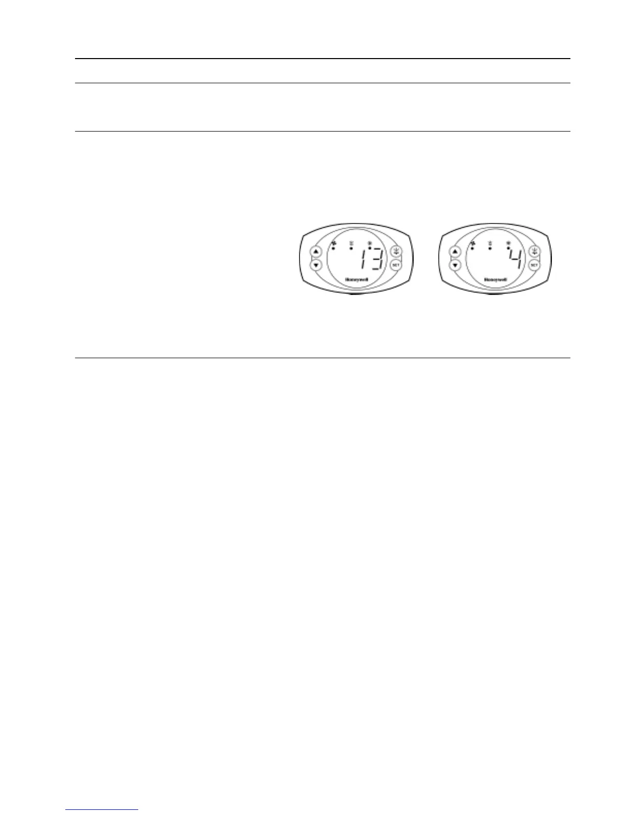
The Icon controller name is displayed as ‘ICXX-Y’ on Genus
®
network. Where ‘XX’
is the STUB number and ‘Y’ is the CASE number.
Fig. 6. Icon identification on Genus
®
Network
8.2. Network Logging-On Procedure
1. Power down controller.
2. Connect network cable to Genus
®
comms module.
3. Insert Genus
®
comms module into the Genus
®
comms socket at the rear of
the Icon controller.
4. Power up controller.
5. After controller power up procedure (5 secs.) enter parameter configuration
setting mode (see section 5.8). Note: Key pad may need to be unlocked
(Depress UP and DOWN keys for 10 seconds until you see ‘Pon’
displayed).
6. Scroll to parameter d27 and enter stub number ‘XX’ e.g. 13
7. Press SET key, the stub number will blink for 5 secs. Icon will then
automatically go to parameter d28 - (case parameter).
8. Enter case number ‘Y’ e.g. 4
9. Press SET key, the case number will blink for 5 secs. Icon will then
automatically go to d29 – (Genus
®
enable / disable parameter).
10. Scroll value to 1 and press SET key which will blink for 5 secs. (Note that if
Value=0 then Icon controller is not linked to Genus
®
system).
11. Wait for Icon to time-out of parameter setting mode (20 secs)
12. Icon will now automatically log-on to Genus
®
front end (PCVisor /
Supervisor)
13. Controller alias will be visible on front-end within 2 minutes.
14. Refer to your front-end literature for further information regarding accessing
Icon via Genus
®
network.
*1: A stub number (XX) represents the refrigeration section where the Icon controller is
situated within the supermarket.
*2: A case number (Y) represents the case within the stub. Also note that the case
representing “K” is displayed as ‘ :- ‘ on the Icon display
Example of Stub number
(0…99) Parameter 27
*1
Example of Case Number
(0…9, A…U) Parameter 28
*2
 Loading...