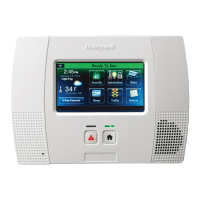
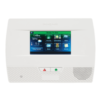
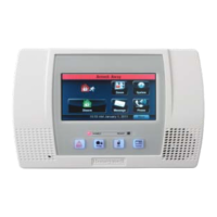
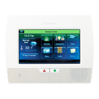
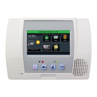
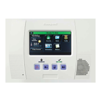
LYNX Touch L5200 Series Control
Quick Installation Guide
This Quick Installation Guide can help you install the rechargeable LYNX Touch Series Control quickly and easily by providing the basic steps for installation using the built-in defaults.
FOR DOCUMENTATION AND ONLINE SUPPORT: http://www.security.honeywell.com/hsc/resources/MyWebTech (see LYNX Touch Series Installation and Setup
Guide P/N 800-16082 or higher.) A copy of the Installation and setup Guide may also be requested from Honeywell.
WARRANTY INFORMATION
For the latest warranty information, please go to:
www.honeywell.com/security/hsc/resources/wa
1. Install the Control
TERMINAL
STRIP
POWER
SUPPLY
RECEPTACLE
BACK
CASE
TAMPER
SWITCH
EDGE
CONNECTOR
WIRE ROUTING
CLIPS (3)
MOUNTING
HOOKS
(HINGES)
5200-100-094-V0
LOCKING TABS
FRONT
CASE
ROTATE
FRONT CASE
UPWARD
TO RELEASE
HOOKS
EDGE
CONNECTOR
ILP5 RECEPTACLE
KNOCKOUT
ILP5
SPACER
BATTERY
CABLE CHANNEL
TIE WRAP
POINTS (3)
MOUNTING
HOLES (4)
TIE WRAP
POINTS (2)
INSTALL
SCREW
IN CASE
TAMPER
CASE
TAMPER
DETAIL A
TELEPHONE
CONNECTIONS
4GL/4GLC OR
GSMVLP5-4G/
GSMVLP5CN4G
RECEPTACLE
2. Make Wiring Connections
5200-100-095-V0
2K
OHM
EOLR
POWER SUPPLY
CONNECTOR
HARD
WIRED
ZONE
WEEKLY TESTING IS REQUIRED TO ENSURE PROPER OPERATION OF THIS SYSTEM
PREMISES
TELEPHONE
INCOMING
PHONE
LINE
H/S T
H/S R
RING
TIP
EGND
EARTH
GROUND
HWZ1
TRIG
GND
GND
+9VDC
STANDARD CAPACITY
BATTERY CONNECTORS
SUPER HIGH CAPACITY
BATTERY CONNECTOR
ZONES
POWER
PHONE
EDGE CONNECTOR
(L5100-ZWAVE)
EDGE CONNECTOR
(L5100-WiFi)
TRIGGER OUTPUT (NEG)
(3ma)
RINGTIP RING TIP
UL NOTE
THE MINIMUM WIRE SIZE USED FOR
TELEPHONE INSTALLATIONS
MUST BE #26 GAGE
OBSERVE POLARITY WHEN CONNECTING
THE POWER SUPPLY TO THE TERMINAL STRIP.
WARNING
TO PREVENT
RISK OF SHOCK,
DISCONNECT
TELEPHONE LINE
AT TELECOM
JACK BEFORE
SERVICING
THIS UNIT
NOTE
USE ONLY THE
300-04705/300-04705V1 or
300-04065/300-04065V1
(300-04063/300-04063V1 or
300-04064/300-04064V1 CANADA)
POWER SUPPLY PROVIDED
300-04705/300-04705V1
OR 300-04065/300-04065V1
(300-04063/300-04063V1
OR 300-04064/300-04064V1
CANADA) POWER SUPPLY
9V, 2.7A
ALL OUTPUT CIRCUITS ARE POWER LIMITED.
4GL/4GLC OR
GSMVLP5-4G/
GSMVLP5CN4G OR
IPL5 RECEPTACLE
Note: For the complete Summary of Connections, refer to the LYNX
Touch Series Installation and Setup Guide P/N 800-16082 or
higher.
3. Install the Communications Module
SIM CARD
5200-100-096-V0
ROTATED
180
ROTATED
180
CONNECTOR
BOARD
CONNECTOR BOARD
CONNECTOR BOARD
RECEPTACLE
LYNX TOUCH
TIE
WRAP
POINT
NOTE:
SIM CARD INSTALLED
IN 4GLT/4GLTC ONLY
REMOVE
ILP5
SPACER
ILP5
SPACER
REMOVE
ILP5
KNOCKOUT
TIE
WRAP
(1)
LYNX TOUCH
ALTERNATE INSTALLATION
RJ45
RECEPTACLE
RJ45 RECEPTACLE
ETHERNET CABLE
SCREW
(3)
ILP5
TO ILP5
4GL/4GLC OR
GSMVLP5-4G/
GSMVLP5CN4G
Ensure that SIM card and the connector board are securely
installed in the communications module before installing it in
the LYNX Touch.
4. Make Battery Connections
5200-100-097-V0
BATTERY PACK
LYNXRCHKIT-SHA
(P/N 300-03866)
OR
RETAINER
SCREW
RETAINER
BATTERY PACK
LYNXRCHKIT-SC
(P/N 300-03864-1)
SCREW
1. Release the front case from the rear case by depressing the two
locking tabs at the top of the unit with the blade of a medium size
screwdriver.
2. Separate the front and back case assemblies by rotating the front
case so that it is perpendicular to the rear case and unsnapping
(releasing) the two hooks (hinges) from the back case.
3. Feed the wiring through the appropriate openings in the back
case. Use tie wraps to secure the wiring to the built-in wire loops
as needed.
4. Mount the back case to a sturdy wall and secure with the provided
screws.
5. If required, install an additional mounting screw in the case
tamper (see Detail A).
6. Attach the front and back cases by connecting the hooks on the
front case to the attachments on back case. Once attached, the
hooks will support the front case and allow you to make the wiring
connections.
7. After all of the wiring connections have been made, snap the front
case and back case closed and ensure that the locking tabs
secure the case.
1. Make earth ground connections to EGND terminal.
2. Connect the incoming phone line to either the 8-position jack or
the TIP and RING terminals.
3. Connect the handset phone lines to the H/S T (TIP) and H/S R
(RING) terminals.
Note: For full line seize operation, refer to the LYNX Touch Series
Installation and Setup Guide.
4 Connect the sensors/contacts to the HWZ1 (+) and GND (-)
terminals.
5. If used, install the 4GL/4GLC or ILP5 communications module
Refer to the Install the Communications Module section or to the
Installation Guide for the Communications Module (P/N 800-
08115 or higher).
6. Connect wires from the 300-04705/300-04705V1, 300-04605/300-
04605 V1 OR 300-04063/3 00-04063V1 OR 300-04064/300-
04064V1 (Canada) Power Supply to GND (-) and +9VDC (+)
terminals OR plug the Power Supply connector into the receptacle
on the LYNX Touch.
1. If you are installing the ILP5 module, use a wire cutter or knife to cut
the plastic tabs that secure the ILP5 spacer to the back case of the
LYNX Touch L5200. If you are installing the 4GL/4GLC module,
proceed to step 3.
2. Remove the ILP5 receptacle knockout from the left side of the
LYNX Touch back case
3 Install the Communications Module into the front case. Ensure that
the connector board is properly seated into the receptacle on the
control.
4 Secure the module with the three provided screws. If you are
installing the ILP5 module, proceed to step 5. If you are installing
the 4GL/4GLC module, proceed to step 8
5. Insert the ILP5 receptacle and spacer into the slot on the back
case.
6. Secure the communications cable to the tie wrap point on the ILP5
with the provided tie wrap.
7. Connect the Ethernet cable to the RJ45 receptacle.
8. Enable the module, configure alarm reporting and module
supervision and register the device. Refer to the “Communications
Diagnostics” section of the LYNX Touch L5200 Installation Guide
(P/N 800-16082 or higher).
1. Insert battery pack into back case.
2. Install battery retainer.
3. Install screw to secure the battery retainer.
4. Connect battery connector to receptacle on PC board.
5. After all wiring connections have been made, snap the front case
to the back case so it is held by the locking tabs.
6. Plug the Power Supply into a 24-hour, 110VAC unswitched outlet.
Note: Rechargeable batteries may take up to 48-hours to fully
charge. “Battery Low” message should clear within four hours,
or by entering Test Mode.
Battery
Part Number
Battery Standby
Time
Minimum
Low Battery Notification
LYNXRCHKIT-SC
(300-03864-1)
4-hours
Approx. 1-hour before
battery depletion
LYNXRCHKIT-SHA
(300-03866)
24-hours
At least 1-hour before
battery depletion
Ê800-16087]Š
800-16087 12/13 Rev. A
2 Corporate Center Drive, Suite 100
P.O. Box 9040, Melville, NY 11747
Copyright © 2013 Honeywell International Inc.
www.honeywell.com/security