2
2. Pull electrical wires through the cover plate (if
used) and subbase cable opening. See Fig. 3.
3. Secure the cover plate (if used) and subbase with the
screws provided. Do not fully tighten the subbase screws.
4. Level the subbase using a spirit level, see Fig. 3, and
firmly tighten subbase mounting screws. The subbase mount-
ing holes provide for minor out-of-level adjustments.
IMPORTANT: An incorrectly leveled subbase will cause
the temperature control to deviate from setpoint. It is
not a calibration problem.
Fig. 2—Installation of Q674 Subbase on wall.
Fig. 3—Subbase components and leveling
procedure.
SPIRIT LEVEL
MOUNTING HOLES (2)
M927
TOP MOUNTING HOLES (2)
WIRING
TERMINAL
THERMOSTAT
CABLE OPENING
TO SPRING FINGER CONTACTS
ON THE THERMOSTAT
(UP TO 12)
POST (2) FOR
MOUNTING
THERMOSTAT
for identification. The terminal barrier permits straight or
conventional wraparound wiring connection. See Fig. 4.
2. Firmly tighten each terminal screw.
3. Fit wires as close as possible to the subbase. Push
excess wire back into hole.
4. Plug hole with nonflammable insulation to prevent
drafts from affecting the thermostat.
Fig. 4—Barrier configuration.
FOR STRAIGHT
INSERTION–
STRIP 5/16 in. [8 mm]
FOR WRAPAROUND–
STRIP 7/16 in. [11 mm]
SUBBASE TERMINAL SCREW
M928
BARRIER
WIRES THROUGH
WALL OPENING
WALL
WALL
ANCHORS
(2)
SUBBASE
MOUNTING
HOLES
MOUNTING
SCREWS
2
M926
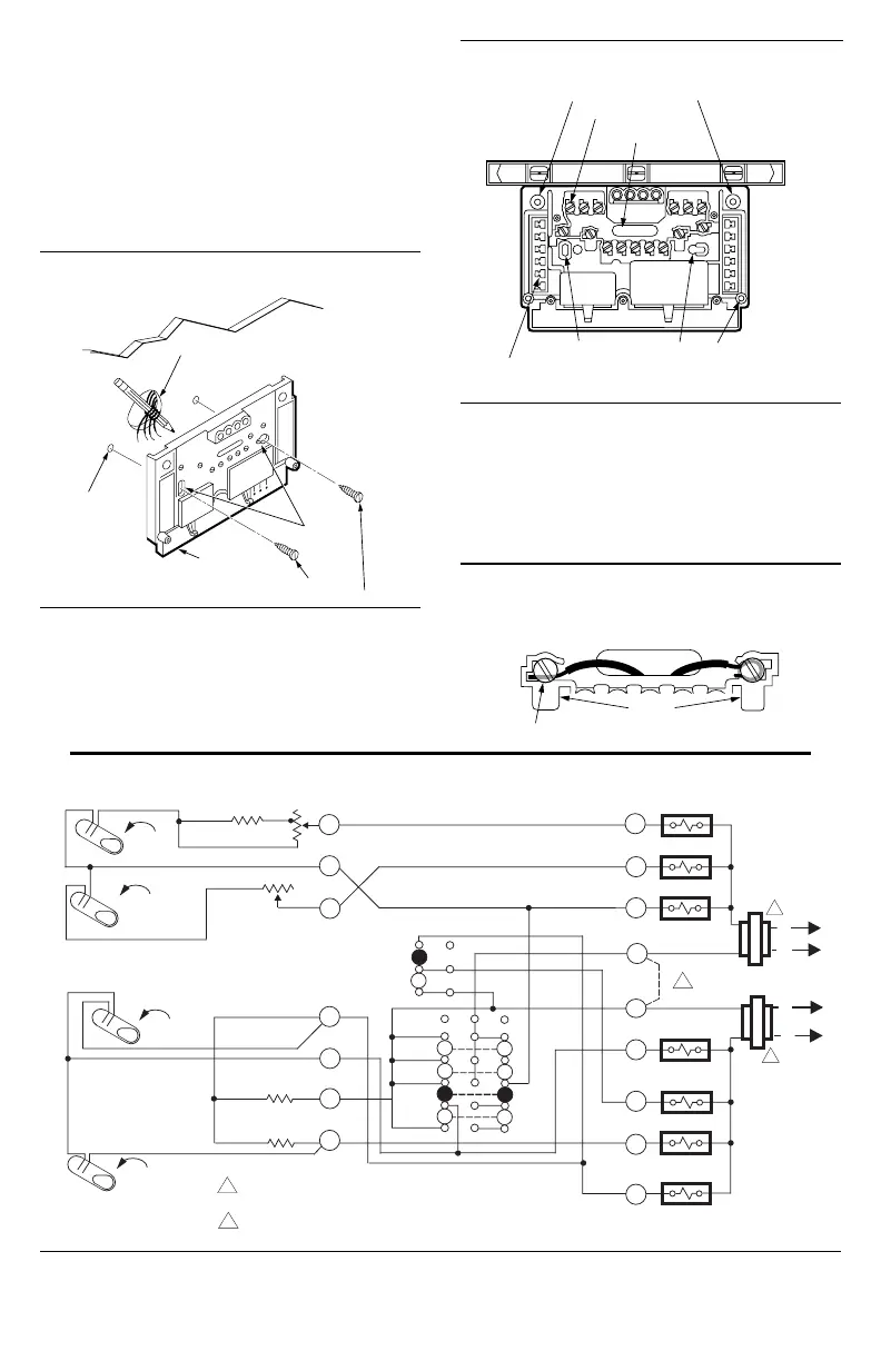
WIRING THE SUBBASE
All wiring must comply with local electrical codes and
ordinances. Follow equipment manufacturer wiring instruc-
tions when available. To wire subbase, proceed as follows:
1. Connect the system wires to the subbase as shown in
Figs. 5 through 8. A letter code is located near each terminal
Fig. 5—Schematic and hookup for T874D Thermostat with Q674E Subbase.
H2 ANTICIPATOR
CHANGEOVER
RELAY (HEAT)
HEAT RELAY 1
RH
W1
HEAT RELAY 2
W2
B
FALL
H2
1
L2
L1
(HOT)
AUTO
ON
FAN
SWITCH
H1
FALL
H1 ANTICIPATOR
M3203
POWER SUPPLY. PROVIDE DISCONNECT MEANS
AND OVERLOAD PROTECTION AS REQUIRED.
JUMPER RC AND RH FOR A SINGLE TRANSFORMER SYSTEM.
1
C1
C1 ANTICIPATOR
CHANGEOVER
RELAY (COOL)
O
Y2
RISE
AUTO
OFF
FAN RELAY
G
COMPRESSOR
CONTACTOR 1
Y1
RC
1
L2
L1
(HOT)
SYSTEM
SWITCH
C2 ANTICIPATOR
C2
RISE
HEAT
COOL
COMPRESSOR
CONTACTOR 2
2
2

 Loading...