59311-1
CAUTION: Turn off all power. Remove instrument by gripping the sides of the
front panel and pulling the instrument out of its housing. Note its orientation.
Option Module 3
Connector PL4B
Option Module 2
Connector PL4A
Option Module A
Connectors PL5 & PL6
Option Module 1
Connectors PL7 & PL8
45 x 45mm
+0.5 –0.0
Panel-Mounting
The mounting panel must be rigid and may be up to 6.0mm
(0.25 inches) thick. The cut-out required for the instrument is
shown on the right. Instruments may be mounted side-by-side
in a multiple installation for which the cut-out width (for n
instruments) is (48n-4)mm or (1.89n-0.16)inches.
Rear Terminal Wiring
USE COPPER CONDUCTORS
(EXCEPT FOR T/C INPUT)
Single Strand wire gauge:
Max 1.2mm (18SWG)
Installing Option Modules
To access modules 1 or A, first detach the PSU and CPU boards from the front moulding by
lifting first the upper, and then lower mounting struts. Gently separate the boards.
a). Plug the required option modules into the correct connectors, as shown below.
b). Locate the tongues on each module into the corresponding slot in the board opposite.
c). Hold the main boards together while relocating them back on the mounting struts.
d). Replace the instrument by aligning the CPU and PSU boards with their guides in the
housing, then slowly push the instrument back into position.
Note: The instrument will automatically detect which option modules have been fitted.
Option Module Connectors
Select mode is used to access the configuration and operation menu functions.
It can be accessed at any time by holding down and pressing .
Once in select mode, press or to select the required mode. An unlock code is
required to prevent unauthorised entry to Configuration, Setup & Automatic Tuning modes.
Press or to enter the correct code number, then press to proceed.
Mode Upper
Display
Lower
Display
Description Default Unlock
Codes
Operator
!"#$ &'(#
Normal instrument operation.
None
Set Up
&)#" &'(#
Tailor settings to the application.
*+
Configuration
(,-. &'(#
Configures the instrument for use.
/+
Product Info
0-., &'(#
Check manufacturing information.
None
Auto-Tuning
1#2- &'(#
Invoke Pre-Tune or Self-Tune.
+
Note: The instrument will always return automatically to Operator mode if there is no
key activity for 2 minutes.
First select Configuration mode from Select mode (refer to section 2).
Press to scroll through the parameters, then press or to set the required value.
To accept a change must be pressed, otherwise parameter will revert to previous value.
To exit from Configuration mode, hold down and press , to return to Select mode.
Note: Parameters displayed depends on how instrument has been configured.
Parameters marked * are repeated in Setup Mode.
Parameter
Lower
Display
Upper
Display
Adjustment range Default
Input Range/Type
0-3#
See following table for possible codes
J T/C
Scale Range
Upper Limit
$2'%
Scale Range Lower Limit +100 to Range Max
Range max
(Lin=1000)
Scale Range
Lower Limit
$''%
Range Min. to Scale Range Upper Limit -100
Range min
(Linear=0)
Decimal point
position
43,&
0=
%
Control Type
(673
421'
Primary & Secondary (heat/cool)%
&-5'
$)2%
Reverse Acting
Primary Output
Control Action
(68'%
40$%
Direct Acting%
$)2
39:0
Process High Alarm
39',%
Process Low Alarm
4;%
Deviation Alarm
<1-4
Band Alarm
Alarm 1Type
1'1*
-,-;
No alarm
39:0
High Alm 1 value*
3=1*
Range Max.
Low Alm 1 value*
3'1*
Range Min. to Range Max
in display units
Range Min.
Band Alm 1 value*
<1'*
1 LSD to span from setpoint in display units
>
Dev. Alm 1 value*
41'*
+/- Span from setpoint in display units
>
Alm 1 Hysteresis*
1:7*
1 LSD to full span in display units
*
Alarm 2 Type*
1'1/ 39',
High Alm 2 value*
3=1/
Range Max.
Low Alm 2 value*
3'1/
Range Min.
Band Alm 2 value*
<1'/
>
Dev. Alm 2 Value*
41'/
>
Alm 2 Hysteresis*
1:7/
Options as for alarm 1
*
Loop Alarm
'1;- 40&1(disabled) or ;-1< (enabled)
40?1
Loop Alarm Time*
'160
1 sec to 99 mins. 59secs
(only applies if primary proportional band = 0)
@@.>@
Parameter
Lower
Display
Upper
Display
Adjustment range Default
-,-)
No alarms Inhibited
1'1*
Alarm 1 inhibited
1'1/
Alarm 2 inhibited
Alarm Inhibit
A-=0
<,#=
Alarm 1 and alarm 2 inhibited
-,-)%
3$0%
Primary (Heat) Power
&)B%
Secondary (Cool) Power
1C94
Alarm 1, Direct
1*9$
Alarm 1, Reverse
1/94
Alarm 2, Direct
1/9$
Alarm 2, Reverse
'394
Loop Alarm, Direct
'39$%
Loop Alarm, Reverse
!$94
Logical Alarm 1 OR 2, Direct
!$9$%
Logical Alarm 1 OR 2, Reverse
1494
Logical Alarm 1 AND 2, Direct
149$
Logical Alarm 1 AND 2, Reverse
$)#&
Retransmit SP Output
Output 1 Usage
D&;*
$)#3
Retransmit PV Output
3$0%
+9>%
0 – 5 V DC output 1
+9*+
0 – 10 V DC output
/9*+
2 – 10 V DC output
+9/+
0 – 20 mA DC output
Linear Output 1
Range
#73*
E9/+
4 – 20 mA DC output
+9*+%
Retransmit Output
1 Scale maximum
$,*:
-1999 to 9999 (display value at which output
will be maximum)
Range max
Retransmit Output
1 Scale minimum
$,*'
-1999 to 9999 (display value at which output
will be minimum)%
Range min
Output 2 Usage
D&;/
Sec or Al2
Lin. O/P 2 Range
#73/
As for output 1
+9*+%
Retransmit Output
2 Scale maximum
$,/:
-1999 to 9999 (display value at which output
will be maximum)
Range max
Retransmit Output
2 Scale minimum
$,/'
-1999 to 9999 (display value at which output
will be minimum)%
Range min
Output 3 Usage
D&;F 1C94%
Linear Output 3
Range
#73F
As for output 1
+9*+%
Retransmit Output
3 Scale maximum
$,F:
-1999 to 9999 (display value at which output
will be maximum)
Range max
Retransmit Output
3 Scale minimum
$,F'
-1999 to 9999 (display value at which output
will be minimum)%
Range min
Display Strategy
40?"
*, /, F, E, > or G
*%
1&(A
ASCII
Mm<-
Modbus with no parity
Mm<;
Modbus with Even Parity
Comms Protocol
3$,#
Mm<,
Modbus with Odd Parity
Mm<-%
*./%
1.2 kbps
/.E
2.4 kbps
E.H
4.8 kbps
@.G
9.6 kbps
Bit rate
<124
*@./%
19.2 kbps
E.H%
Comms Address
144$ %*%
1 –255 (Modbus), 1-99 (ASCII)
*%
Comms Write
(,;-
Read only or read/write
r_ Ww
40&*
Setpoint 1 / Setpoint 2 select
Digital Input
Usage
4050
401?
Automatic / Manual select
40&*%
Config Lock Code
(',B%
0 to 9999
/+%
Note: Refer to the full user guide (available from your supplier) for further details on
these parameters.
CAUTION: Do not remove the panel gasket; it is a seal against dust and
moisture.
CAUTION: Installation and configuration should be performed only by
personnel who are technically competent to do so. Local Regulations regarding
electrical installation & safety must be observed.
1. INSTALLATION
Hold instrument firmly in position
(apply pressure to bezel only)
Mounting Panel
Instrument Housing
Ratchets
Gasket
Slide mounting clamp over the
instrument housing towards rear face
of mounting panel until the tongues
engage in ratchets and instrument is
clamped in position.
2. SELECT MODE
3. CONFIGURATION MODE
CPU PCB
Option Module 1
Option Module 2
Option Module
Option Module 3
PSU PCB
Mounting Struts
CAUTION: Check information label on
housing for correct operating voltage
before connecting supply to Power Input
Fuse: 100 – 240V ac – 1amp anti-surge
24/48V ac/dc – 315mA anti-surge
CAUTION: Diagram shows all possible
combinations. Actual connections required
depends on exact model and options fitted.
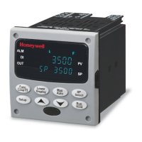
HONEYWELL UDC1200 MICRO-PRO
Universal Digital Controller Product Manual (51-52-25-123-EN)