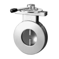
MANUALLY OPERATED BUTTERFLY VALVE
VF5000 Series
INSTRUCTION SHEET
UNIVERSAL GAS VALVES
MU1R--9147 9610R0--NE
APPLICATION
These series manually operated butterfly valves are used to
control and govern the burner airlock of gas burners. The
VF5000 Series can be equipped with the MT4000 Series
and MF4000 Series servomotors. The choice of the servo
motor depends on the working pressure and size of the
butterfly valve. The MF4000 Series is typically used in 360
mbar maximum working pressure applications and on sizes
DN50 and larger.
SPECIFICATIONS
Models
VF5000A3
Dimensions
See Figure. 1. Installation drawing VF5000A on page 2.
Pipe sizes
Inlet and outlet flanged connection DN25 up to DN150
according to PN16 ISO 7005--1.
Capacity
See Fig. 2. Capacity curves VF5000A Series on page 5.
Maximum operating pressure
500 mbar
Torsion and bending stress
Pipe connections meet group 2 according to EN161
requirements.
Ambient temperature range
--15 ... 100 °C
Valve body
Aluminium alloy die--cast
Standards and Approvals
The VF5000 Series manually operated butterfly valves
conform with the following EC directives:
• Gas Appliance Directive (90/396/EEC)
PIN: CE--0063AR1583
INSTALLATION
See Figure 1. Installation drawing VF5000A on page 2.
IMPORTANT
1. Read these instructions carefully, failure to follow
the instructions could damage the product or
cause hazardous condition.
2. Check the ratings given in the instructions and on
the product to make sure the product is suitable
foryourapplication.
3. The installation has to be carried out by qualified
personnel only.
4. Carry out a thorough checkout when installation
is completed.
Mounting and orientation
The gas valve can be mounted in all positions (only without
motor).
Mounting location
Thedistancebetweenthegasvalveandwall/groundmustbe
at least 30 cm.
WARNING
!
Turn off gas supply before installation.
Main gas connection
1. Take care that dirt does not enter the gas valve during
handling
2. Place the gaskets. If necessary grease it slightly to
keep it in place.
3. Mount the gas valve between the flanges using the
bolts for each flange.
Subject to change without notice. Printed in the Netherlands.