2
4. Install the Switch Hardware (Continued)
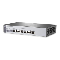
Wall or Under-Table: Use a #1 Phillips (cross-head) screwdriver
to attach the supplied brackets to the switch using the eight 8-mm
M4 screws in the orientation shown.
For wall-mounting, the network ports must be facing up or down.
Do not mount the switch with ventilation or fan ducts facing up or
down. (See “Installation Precautions” on page 4.)
Attach the switch to the wall or wood surface with four 5/8-inch
number 12 wood or tap screws (not included).
5. Power On the Switch.
6. Configure the switch for operation on your network
(minimal configuration).
Using a standard Ethernet cable, connect a PC directly to the
switch.
Then configure the PC’s IP Address and Subnet Mask to allow it to
communicate with the switch through your PC’s Web browser.
See the example on page 3.
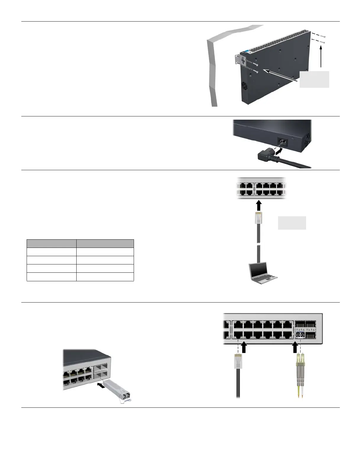
7. Connect Network Cables.
Note: For transceiver connections, install and use only
HP mini-GBIC/SFP transceivers supported by the switch.
See “Mini-GBIC/SFP Installation Notes” on page 3.
Switch factory-default settings:
Parameter Factory Default Setting
Password <blank>
IP address 192.168.2.10
Subnet mask 255.255.255.0
Default gateway not set
 Loading...