Chapter 3 207
Assembly Replacement
Procedure 13. Rear Frame/Rear Dress Panel
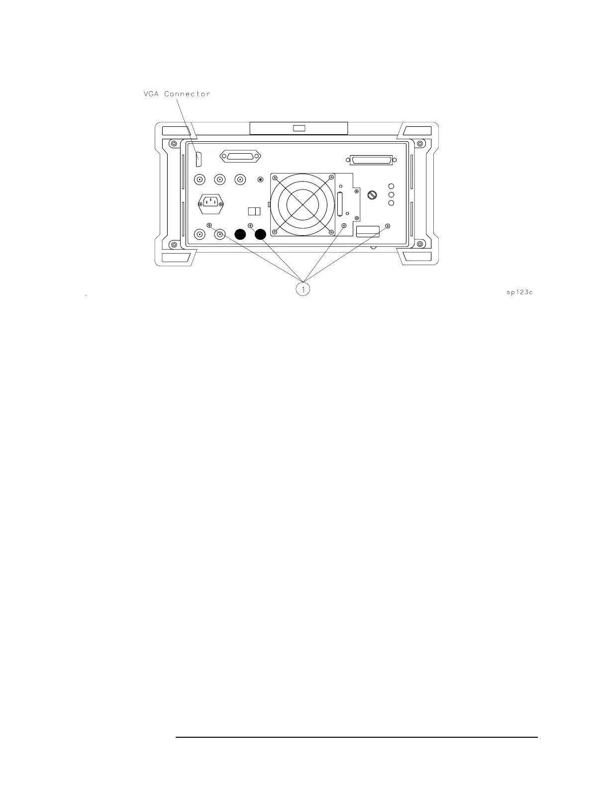
Figure 3-29 Main Deck Screws
Replacement
1. If the rear dress panel is removed, secure it to the rear frame using
two nuts. Ensure that the dress panel is aligned with the frame.
2. Place the spectrum analyzer on its front panel allowing easy access
to the rear-frame area.
3. Place the rear frame on the spectrum analyzer and secure the
knurled nut on the earphone jack. A lock washer should be used on
the inside of the rear frame and a flat washer on the outside.
4. Place the coax cable's BNC connectors into the appropriate
rear-frame holes as described below. Use a 9/16-inch nut driver to
attach the dress nuts holding the BNC connectors to the rear frame.
5. Secure the rear frame to the spectrum analyzer main deck, using
four panhead screws (1). See Figure 3-29.
Rear Panel Jack
EC-series E-series RF Cable
J1 n/a W64
n/a J1 W55
J4 J4 W24, coax 5
J5 J5 W23, coax 93
J6 J6 W25, coax 4
J7 n/a W55
J8 J8 W18, coax 97
J9 J9 W31, coax 8
J11 J11 W58, coax 8

 Loading...


