Chapter 3 217
Assembly Replacement
Procedure 14. W3 Line Switch Cable (8560E)
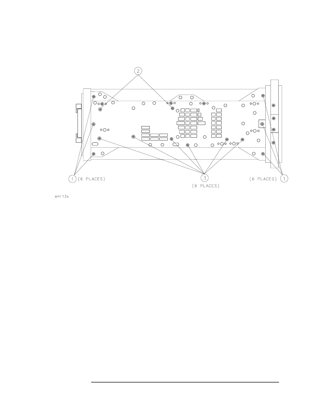
Figure 3-34 Side Frame Mounting Screws
7. On the top side of the spectrum analyzer, redress W3.
8. Connect W3 to A6J2. Dress W3 into the slotted opening in the deck.
9. Connect A1A1W1 to A3J602.
10.Secure the power supply cover shield to the power supply using
three flathead screws. One end of the cover fits into a slot provided in
the rear frame assembly. Ensure that the extended portion of the
cover shield is seated in the shield wall groove. See Figure 3-30 on
page 209.
11.Place W3 and the other cable assemblies between the CRT assembly
and the power supply cover so the W9 wires are underneath the
surface of the power supply cover.
12.Fold up the A2, A3, A4, and A5 assemblies into the spectrum
analyzer as described in steps 5 through 10 under "Procedure 5. A2,
A3, A4, and A5 Assemblies Replacement."
13.Fold up A14 and A15 assemblies as described in steps 3 through 5
under "Procedure 9. A14 and A15 Assemblies Replacement."
14.Replace the spectrum analyzer cover assembly.

 Loading...


