604 Chapter11
RF Section
A15 RF Assembly
9. If the signals are correct in EXTernal operation, but not in INTernal
operation, the problem lies in A21 OCXO (or Option 103 TCXO), its
voltage reference, or the TTL level generator. Check these areas as
follows:
a. On the HP 8560E/EC, press
10 MHz INT.
b. Check U305 pin 3 for approximately +12 Vdc (Option 103 only).
c. Check for a 10 MHz sine wave greater than or equal to 1 V p-p at
J305 (standard HP 8563E), or at U302 pin 3 with an oscilloscope
(Option 103).
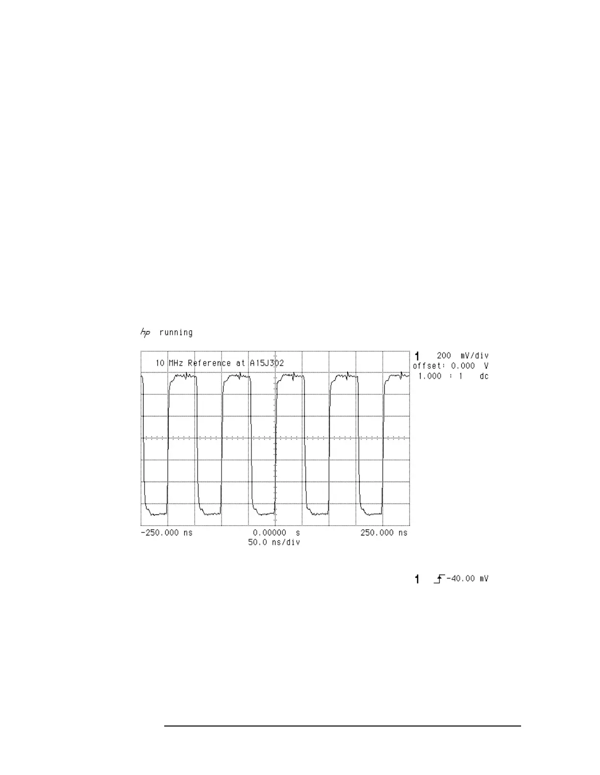
10.If the signal at U304 pin 13 is correct (see Figure 11-4 on page 605),
but there is a problem with the signals at A15J301, A15J302,
A15J303, or A15J304, suspect U303 or U304 in the 10 MHz
distribution circuitry.
Figure 11-3 10 MHz Reference at A15J302

 Loading...


