EL-MF877-00 Page 2
Template Revision A
Tool Size (if
applicable)
3.0 Product Disassembly Process
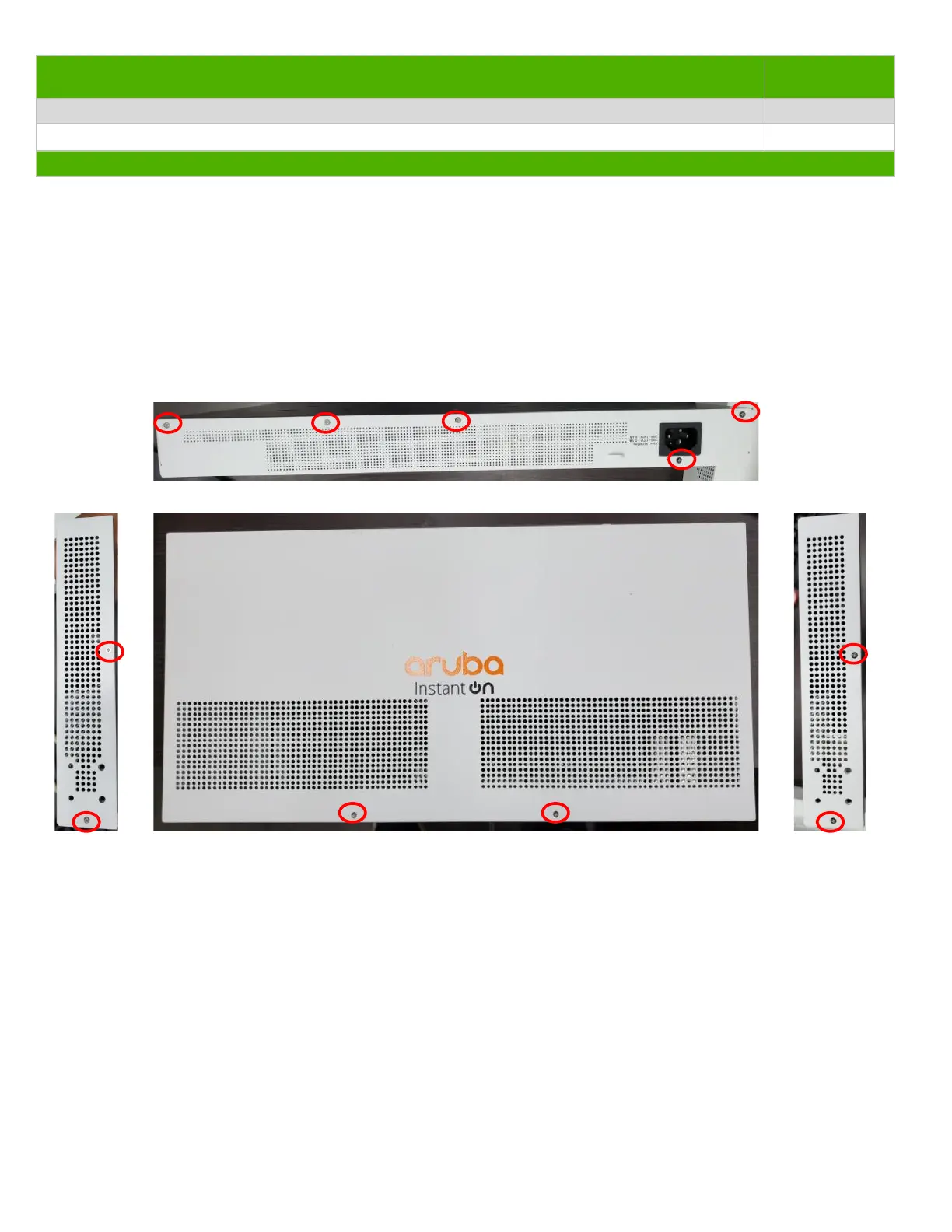
1. Using a P1 Phillips Screw Driver, remove all 11 screws securing top cover to chassis. Remove cover. (see 3.2.1)
2. Disconnect Power supply and main board cable connections (1 cable connection in all)(see 3.2.2)
3. Using a P2 Phillips Screw Driver, remove 4 screws to chassis, remove Power supply.(see 3.2.3)
4. Using a P2 Phillips Screw Driver, remove 15 screws to chassis ,remove main board (1pcs) and light-pipe (1pcs).(see 3.2.4)
5. Cut ac-inlet materials (use Diagonal pliers) and Using a P2 Phillips Screw Driver, remove 1 screws to chassis and Disconnect
ac-inlet cable(see 3.2.5)
3.2 Optional Graphic. If the disassembly process is complex, insert a graphic illustration below to identify the items
contained in the product that require selective treatment (with descriptions and arrows identifying locations).
3.2.1
3.2.2
 Loading...