Heat Sink Removal
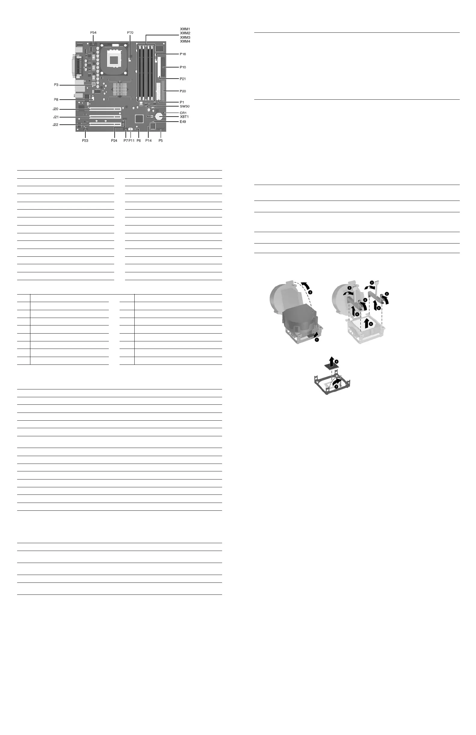
System Board Connectors and Jumpers (position of some untitled components may vary in location)
CR1 5V_Aux LED P16 Power supply fan control
E49 Password jumper P20 Primary IDE
J20 PCI slot 1 P21 Secondary IDE
J21 PCI slot 2 P23 Front panel audio connector
J22 PCI slot 3 P24 Front panel USB connector
P1 Main power (20 pin) P54 Serial Port “B”
P3 CPU regulator power (4 pin) P70 CPU fan
P5 Front panel SW50 CMOS button
P6 Internal chassis speaker XBT1 Battery
P7 CD audio in XMM1 Memory socket
P8 Chassis fan XMM2 Memory socket
P10 Diskette drive XMM3 Memory socket
P11 Aux audio in XMM4 Memory socket
P14 Boot block
System Hardware Interrupts
IRQ
System Function IRQ System Function
0
Timer Interrupt 8 Real-Time Clock
1
Keyboard 9 Unused
2
Interrupt Controller Cascade 10 Unused, available for PCI
3
Serial Port (COM B) 11 Unused, available for PCI
4
Serial Port (COM A) 12 Mouse
5
Unused, available for PCI 13 Coprocessor
6
Diskette Drive 14 Primary ATA (IDE) Controller
7
Parallel Port (LPT 1) 15 Secondary ATA (IDE) Controller
Computer Diagnostic LEDs (on front of computer)
LED Color LED Activity State/Message
Power Green On (S0) Computer on
Power Green 1 blink every 2 seconds (S1) Suspend Mode
Power Green 1 blink every 2 seconds (S3) Suspend to RAM
Power Green Off (S4) Suspend to Disk (if applicable)
Power Clear Off (S5) Computer off
Power Red 1 blink followed by 2-second
pause - Repeat
Power Supply failure
Power Red* 2 blinks 1 second apart CPU thermal shutdown
Power Red* 3 blinks 1 second apart CPU not installed
Power Red* 4 blinks 1 second apart Power supply overload ( crow bar)
Power Red* 5 blinks 1 second apart No memory
Power Red* 6 blinks 1 second apart No graphics
Power Red* 7 blinks 1 second apart System board failure (detected prior to video)
Power Red* 8 blinks 1 second apart Invalid ROM
Hard Drive Green Blinking Hard drive activity
*Blinking codes are repeated after a 2 second pause.
Keyboard Diagnostic LEDs, PS/2 Keyboards Only
LED Color LED Activity State/Message
Num, Caps,
Scroll Lock
Green On (Rising Tone) ROM reflashed successfully
Num Lock Green On ROMPaq diskette not present, is bad, or drive
not ready.*
Caps Lock Green On Enter password.
Num, Caps,
Scroll Lock
Green Blink On in sequence, one at a
time - N, C, SL
Keyboard locked in network mode
* Insert valid ROMPaq diskette in drive A. Turn power switch off, then on to reflash ROM. If ROM flash is successful, all
three keyboard LEDs will light up, and you will hear a rising tone series of beeps. Remove diskette and turn power off,
then on to restart the computer. For more information about flashing the ROM, refer to the Troubleshooting guide.
Clearing CMOS
The computer's configuration (CMOS) may occasionally be corrupted. If it is, it is necessary to clear the CMOS
memory using switch SW50.
To clear and reset the configuration, perform the following procedure:
1. Prepare the computer for disassembly.
Ä
CAUTION: The power cord must be disconnected from the power source before pushing the Clear CMOS
Button (NOTE: All LEDs on the board should be OFF). Failure to do so may damage the system board
2. Remove the access panel.
3. Press the CMOS button located on the system board and keep it depressed for 5 seconds.
4. Replace the access panel.
5. Turn the computer on and run F10 Computer Setup (Setup-utility) to reconfigure the system.
Disabling or Clearing the Power-On and Setup Passwords
1. Turn off the computer and any external devices, and disconnect the power cord from the power outlet.
2. Remove the access panel.
3. Locate the header and jumper labeled E49.
4. Remove the jumper from pins 1 and 2. Place the jumper over pin 2 only, in order to avoid losing it.
5. Replace the access panel.
6. Plug in the computer and turn on power. Allow the operating system to start.
NOTE: Placing the jumper on pin 2 clears the current passwords and disables the password features.
7. To re-enable the password features, repeat steps 1-3, then replace the jumper on pins 1 and 2.
8. Repeat steps 5-6, then establish new passwords.
Refer to the Computer Setup (F10 Setup) instructions to establish new passwords.
Computer Setup (F10) Utility Features (not all features may be available)
File
System Information
About
Set Time and date
Save to Diskette
Restore From Diskette
Set defaults and Exit
Ignore Changes and Exit
Save Changes and Exit
Storage
Device Configuration
Options
IDE DPS Self-Test
Controller Order
Boot Order
Security
Setup Password
Power-On Password
Password Options
DriveLock
Master Boot Record Security
Save Master Boot Record
Restore Master Boot Record
Device Security
Network Service Boot
System IDs
Advanced
Power-On Options
Onboard devices
PCI Devices
Bus Options
Device Options
PCI VGA Configuration
Note: For more information see Computer Setup (F10) Utility Guide on the Documentation Library CD.
 Loading...