EL-MF877-00 Page 2
Template Revision A
2.0 Tools Required
List the type and size of the tools that would typically be used to disassemble the product to a point where components
and materials requiring selective treatment can be removed.
Tool Description Tool Size (if
applicable)
Description #1 screw driver philip #1
Description #2
Description #3
Description #4
Description #5
3.0 Product Disassembly Process
3.1 List the basic steps that should typically be followed to remove components and materials requiring selective treatment:
1. Remove battery module
2. Remove HDD & RAM & MINICARD door.
3. Remove HDD module
4. Remove expansion memory
5. Remove Mini-CARD
6. Remove ODD assembly
7. Remove Keyboard
8. Remove strip cover (with power button PCB & Capacitive PCB)
9. Divide strip assy (with speaker mesh & KB deck)
10. Remove LCD cable and antenna
11. Divide LCD assembly from base assembly
12. Divide logic-up assembly(with TP module & Speaker module) from base assembly
13. Divide M/B(with CPU and memory and thermal module) from base assembly
14. Remove Fan assembly from logic lower.
15. Remove DC IN cable wire & RJ11&Tv_tuner wire from logic-low assembly
16. Divide LCD cover & LCD bezel.
17. Divide LCD panel and Hinge Bracket.
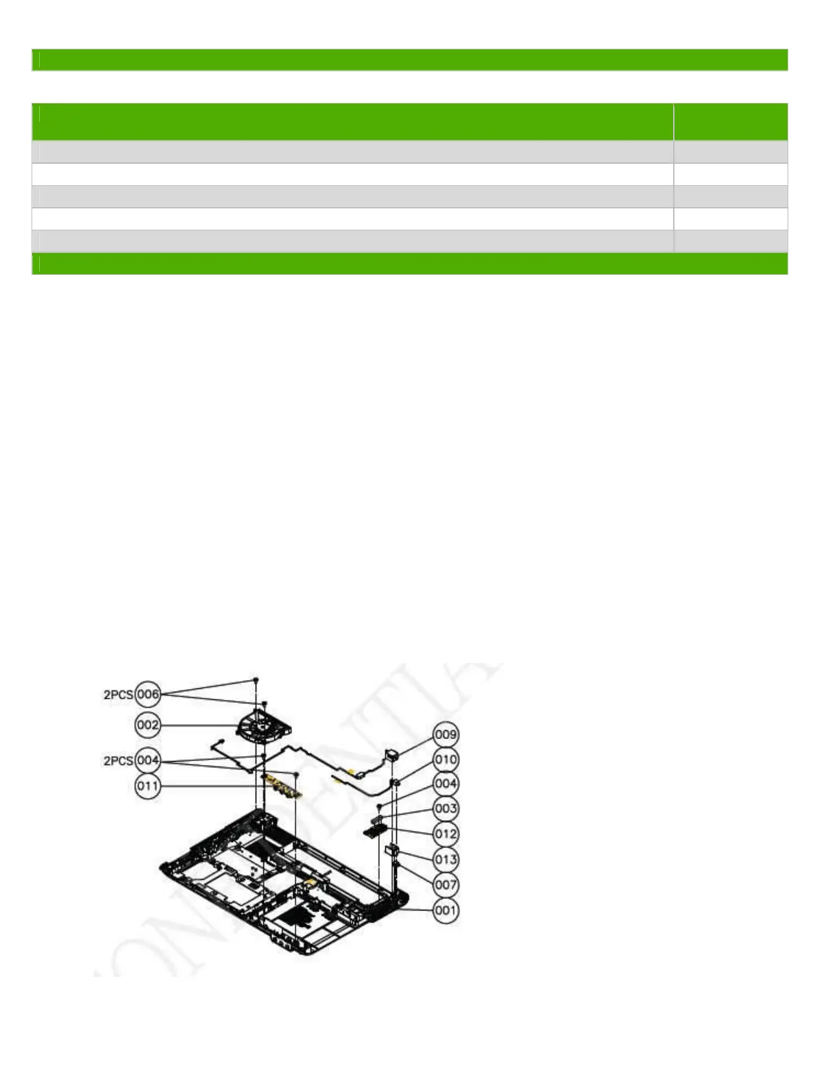
3.2 Optional Graphic. If the disassembly process is complex, insert a graphic illustration below to identify the items
contained in the product that require selective treatment (with descriptions and arrows identifying locations).
 Loading...