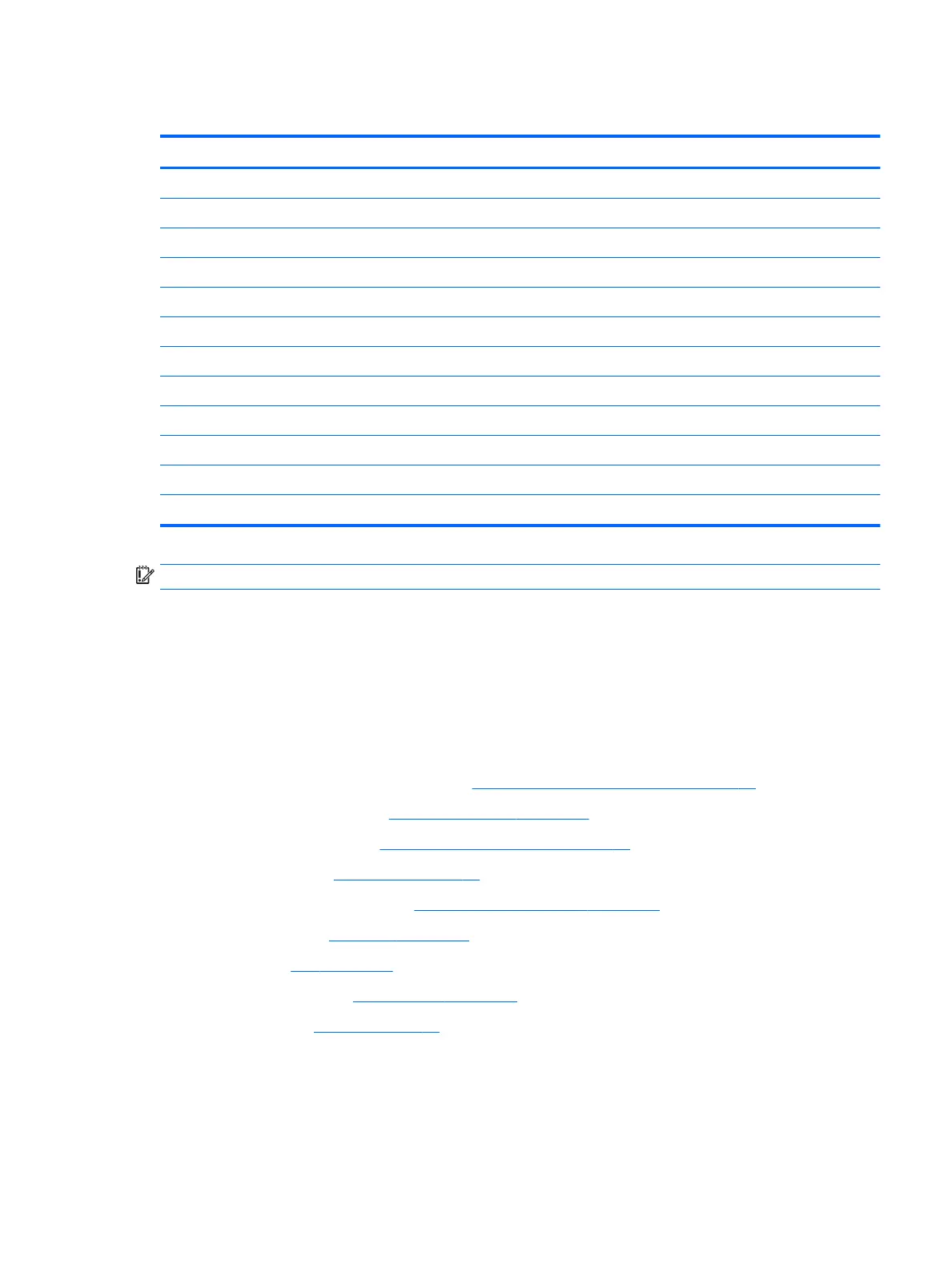
System board
Description Spare part number
System board
UMA graphics Core M-7Y30 4 GB with Windows operating system and WLAN capability 918345-601
UMA graphics Core i5-7Y54 4 GB with Windows operating system and WLAN capability 918346-601
UMA graphics Core i5-7Y54 8 GB with Windows operating system and WLAN capability 918347-601
UMA graphics Core i5-7Y57 4 GB with Windows operating system and WLAN capability 918348-601
UMA graphics Core i5-7Y57 8 GB with Windows operating system and WLAN capability 918349-601
UMA graphics Core i7-7Y75 8 GB with Windows operating system and WLAN capability 918350-601
UMA graphics Pentium 4410Y 4 GB with Windows operating system and WLAN capability 918351-601
USB Type-C bracket (included with the Plastics Kit) 918392-001
POGO connector (includes cable) 918389-001
Microphone board 918387-001
Front webcam 918906-001
IMPORTANT: Make special note of each screw size and location during removal and replacement.
Before removing the system board, follow these steps:
1. Turn o the computer. If you are unsure whether the computer is o or in Hibernation, turn
the computer on, and then shut it down through the operating system.
2. Disconnect the power from the computer by unplugging the power cord from the computer.
3. Disconnect all external devices from the computer.
4. Remove the following components:
a. Keyboard (select products only) (see Keyboard (select products only) on page 31)
b. Micro SIM card tray (see Micro SIM card tray on page 32)
c. MicroSD card tray (see MicroSD memory card tray on page 33)
d. Rear cover (see Rear cover on page 34)
e. Disconnect the battery (see Disconnecting the battery on page 35)
f. Kickstand (see Kickstand on page 36)
g. SSD (see SSD on page 38)
h. Display panel (see Display panel on page 45)
i. Battery (see Battery on page 49)
Remove the system board:
1. Remove the 2 Phillips M1.6x2.0 screws (1) securing the POGO cable.
2. Use a thin tool (2) to release the POGO cable from the glue securing it.
Component replacement procedures 55