Section I
Paragraphs 1-3 to l-12
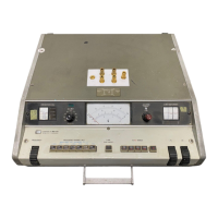
Model 4342A
user convenience, have broad applications
in testing components and electronic mate-
rials, in physical and chemical research, and
in related scientific fields.
Pushbutton operation of frequency range and
Q/AQ range selection provides for straight-
forward measurement.
Automatic indication of
meter scales,
frequency dials, and frequency
multipliers are used,
adding to the simplicity
and reading speed.
l-3. How The 4342A Measures.
l-4. The Q Meter is basically composed of a
stable, variable oscillator, a tuning circuit
for taking resonance with an unknown sample,
and a high input impedance RF voltmeter con-
nected across the variable capacitor which is
a section of the tuning circuit.
To measure the quality factor of a sample, a
stable oscillator signal is injected into the
series tuning circuit composed of the vari-
able capacitor and the unknown (inductor).
At the tuned frequency, the RF voltmeter
(called Q voltmeter) indicates a peak value
in the signal level increase (resonance) and
is proportional to the quality factor of the
sample measured.
By injecting an oscillator
signal with a low output impedance and by
measuring the signal level of the series re-
sonant circuit with a high impedance volt-
meter, the quality factor of the unknown
samnle can be accurately determined at the
resonant frequency.
Additionally, various
parameters of the sample can be measured
(directly and indirectly) as factors of the
resonant frequency and the tuning capacity
which can be read from their respective dial
scales.
l-5. For accurate measurements, the 4342A
employs a unique constant voltage injection
system and a low output impedance injection
transformer. The oscillator signal is auto-
matically leveled by an ALC loop to provide
the constant injection voltage required by
the Q range in use.
This obviates the need
of an oscillator level control or the fragile
thermocouple level meter (as used in tradi-
tional Q Meters).
The unique injection
transformer along with the high quality low
loss tuning capacitor contribute minimal addi-
tional loss to the measurement circuit (reso-
nant circuit) and greatly improve the Q ac-
curacy in high Q measurements.
l-6. High stability of the Q voltmeter vir-
tually eliminates the need for Q-zero adjust-
ments in routine measurements. Troublesome
zero settings prior to each adjustment are
thus eliminated, ensuring simple and rapid op-
eration. Accurate determination of Q changes
l-2
in delta-Q measurements can be obtained in all
Q ranges by using the expanded resolution
(X10) capability.
l-7. The unique Q Limit selector is espe-
cially useful in Go/No-Go checking on the
production line. The high response speed of
the Go/No-Go indicator (compared to using a
meter pointer deflection method) permits
faster Go/No-Go testing. For even easier
testing, external indicating devices may be
remotely controlled by the Go/No-Go output
signal (on the rear panel).
1-8. INSTRUMENTS COVERED BY MANUAL.
l-9. Hewlett-Packard uses a two-section
nine character serial number which is marked
on the serial number plate (Figure 1-2) at-
tached to the instrument rear panel.
The
first four digits and the letter are the se-
rial prefix and the last five digits are the
suffix. The letter placed between the two
sections identifies country where instrument
was manufactured.
The prefix is the same for
all identical instruments; it changes only
when a change is made to the instrument.
The
suffix, however,
is assigned sequentially
and is different for each instrument.
The
contents of this manual apply to instruments
with the serial number prefix(es) listed
under SERIAL NUMBERS on the title page.
l-10. An instrument manufactured after the
printing of this manual may have a serial
number prefix that is not listed on the title
page.
This unlisted serial number prefix in-
dicates that the instrument is different from
those described in this manual. The manual
for this new instrument may be accompanied by
a yellow Manual Changes supplement or have a
different manual part number. This supple-
ment contains
"change information" that ex-
plains how to adapt the manual to the newer
instrument.
l-11. In addition to change information, the
supplement may contain information for cor-
recting errors (called Errata) in the manual.
To keep this manual as current and accurate
as possible, Hewlett-Packard recommends that
you periodically request the latest Manual
Changes supplement. The supplement for this
manual is identified with this manual's title
page.
Complimentary copies of the supplement
are available from ltewlett-Packard. If the
serial prefix or number of an instrument is
lower than that on title page of this manual,
see Section VII Manual Changes.
1-12.
For information concerning a serial
number prefix that is not listed on the title
page or in the Manual Changes supplement,
contact your nearest Hewlett-Packard office.

