Pin on the RJ45
Connector
Wire Color Wire Type Pin on the RJ45 Connector
X1.7 White X2.7
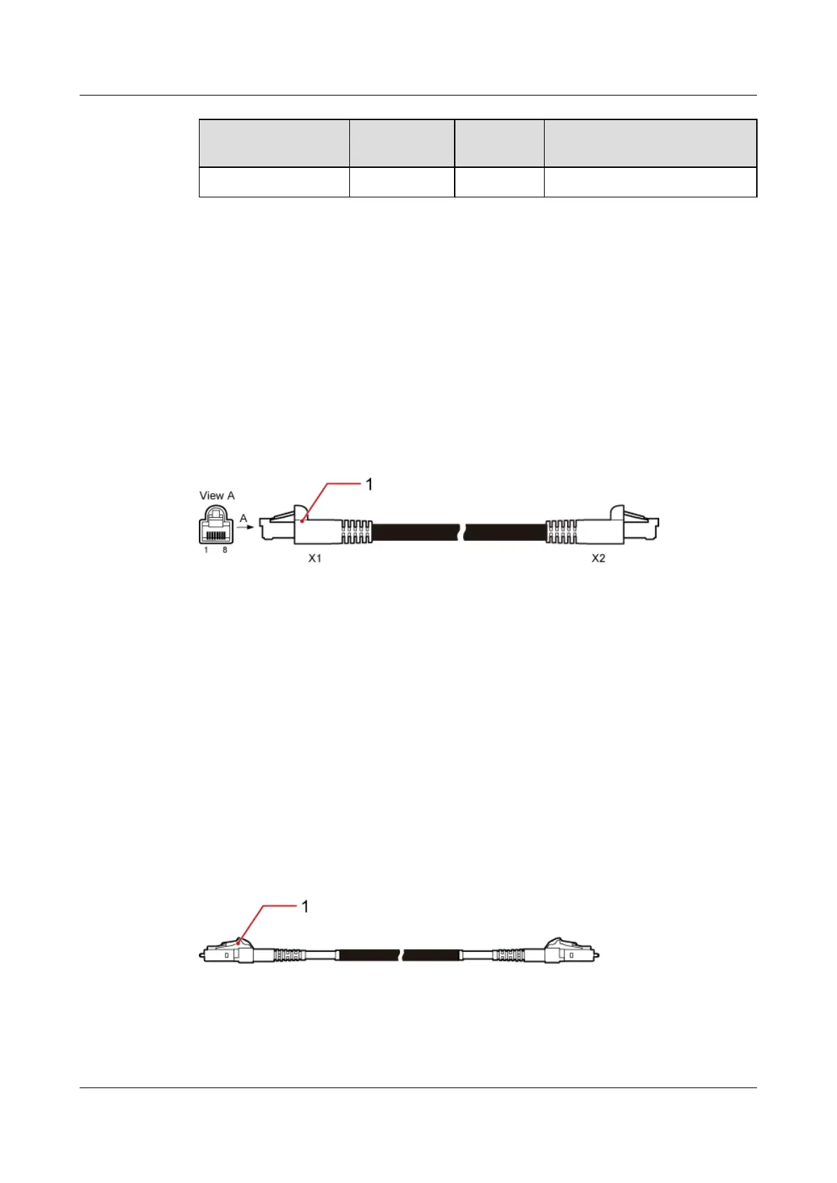
7.6.5 Interconnection Cable Between the FE Electrical Ports
This cable connects the FE electrical ports on two main control boards to enable IP-based co-
transmission.
Exterior
The interconnection cable between the FE electrical ports has an RJ45 connector at each end,
as shown in Figure 7-29.
Figure 7-29 Interconnection cable between FE electrical ports
(1) RJ45 connector
7.6.6 Interconnection Cable Between FE Optical Ports
This cable connects the FE optical ports on the GTMU and WMPT to achieve co-transmission
in IP mode.
Exterior
The interconnection cable between the FE optical ports has an LC connector at each end, as
shown in Figure 7-30.
Figure 7-30 Interconnection cable between FE optical ports
(1) LC connector
BTS3900C (Ver.C)
Hardware Description 7 BTS3900C Cables
Issue 03 (2013-05-27) Huawei Proprietary and Confidential
Copyright © Huawei Technologies Co., Ltd.
159