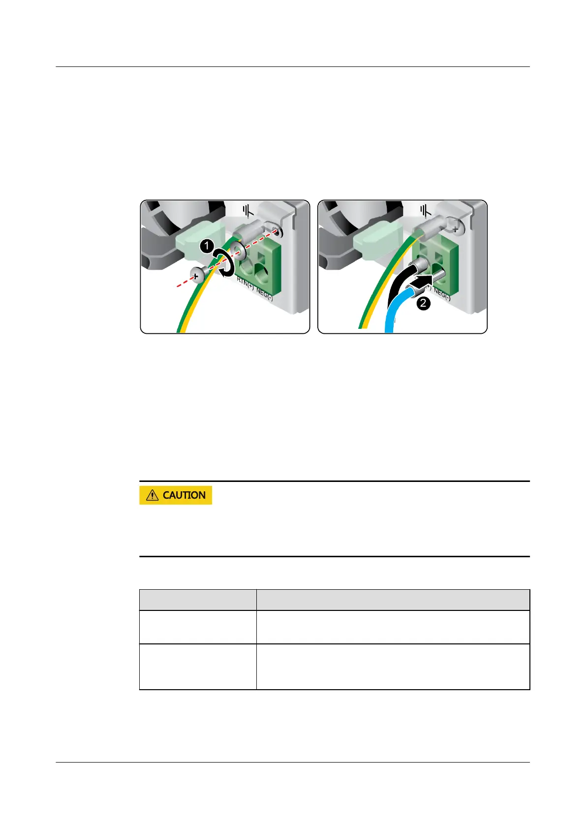
2. Insert the power cables to the wiring terminals on the PSU until the cables
click into position. See (2) in Figure 7-24.
– Connect the cord end terminal of the negative power cable (blue) to the
NEG(-) wiring terminal on the PSU.
– Connect the cord end terminal of the positive power cable (black) to the
RTN(+) wiring terminal on the PSU.
Figure 7-24 Connecting cables
Step 3 Connect the other end of the power cable to the DC PDU in the cabinet.
The DC PDU is fastened horizontally in the rear of the cabinet. Connect the power
cable to the socket on the PDU according to the plan.
Step 4 Bundle the power cables to the cable guide using cable ties.
----End
7.2.6.8 Checking Cable Connections
Before checking cable connections, ensure that the power is cut o. Otherwise,
any incorrect connection or loose connection may cause human injury or device
damage.
Table 7-3 Cable connection checklist
Item
Description
Power cable Power cables are correctly connected to the rear of the
chassis.
Network cable Network cables are connected correctly to the
management port or service ports on the rear panel of
the chassis.
FusionServer Pro 2288X V5 Server
User Guide 7 Installation and Conguration
Issue 04 (2020-06-05) Copyright © Huawei Technologies Co., Ltd. 94

 Loading...